Using The Following Circuit Design A Mod 10 Up And Chegg

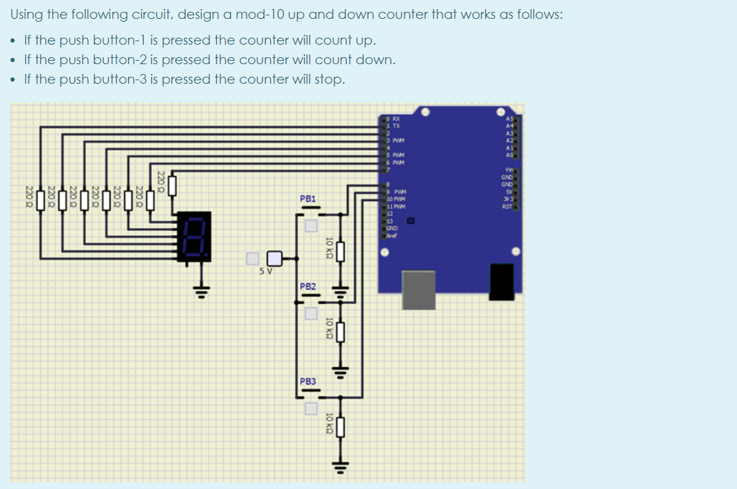
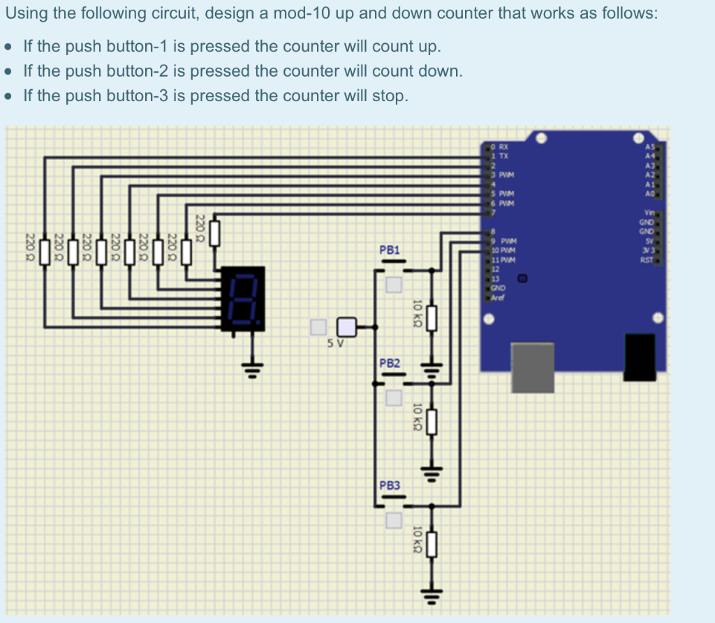
Using The Following Circuit Design A Mod 10 Up And Chegg Using the following circuit, design a mod 10 up and down counter that works as follows: • if the push button 1 is pressed the counter will count up. • if the push button 2 is pressed the counter will count down. • if the push button 3 is pressed the counter will stop. Part a asks to design a mod 10 up ripple counter using negative edge triggered jk flip flops, including a timing diagram and truth table. part b asks to analyze a given circuit.

Using The Following Circuit Design A Mod 10 Up And Chegg Implement a jk flip flop with a t flip flop and a minimal and or not network. let us assume that the complements of j, k and q signals are available. draw the logic diagram to show your design. (design specification) write the state table of the sequential circuit as the following figure. a. write the state table. b. This combination of a mod 10 up asynchronous counter and a seven segment display is commonly used in digital electronics for applications such as digital clocks, timers, and other devices where a visual representation of numeric values is required. Using the following circuit, design a mod 10 up and down counter that works as follows: if the push button 1 is pressed, the counter will count up. if the push button 2 is pressed, the counter will count down. Shift registers: draw only logic diagram of sipo. (2m) design a mod 10 synchronous counter. (note: other relevant flip flop can be used) number of desired states = 10 number of flip flops required= 4 [ 2n m] use jk flip flop draw the k maps for the respective inputs in terms of ouputs.

Using The Following Circuit Design A Mod 10 Up And Chegg Using the following circuit, design a mod 10 up and down counter that works as follows: if the push button 1 is pressed, the counter will count up. if the push button 2 is pressed, the counter will count down. Shift registers: draw only logic diagram of sipo. (2m) design a mod 10 synchronous counter. (note: other relevant flip flop can be used) number of desired states = 10 number of flip flops required= 4 [ 2n m] use jk flip flop draw the k maps for the respective inputs in terms of ouputs. The typical way an up down counter is designed is to start with a truth transition table, draw some kmaps, and solve for the boolean equations. when you use this method, you don't need to use the set reset inputs on the flip flops. To design the combinational circuit of valid states, following truth table and k map is drawn: from the above truth table, we draw the k maps and get the expression for the mod 10 asynchronous counter. If the push button 1 is pressed the counter will count up. • if the push button 2 is pressed the counter will count down • if the push button 3 is pressed the counter will stop. Synchronous mod n counters: here, we have some examples for designing synchronous mod n counters in digital electronics.

Using The Following Circuit Design A Mod 10 Up And Chegg The typical way an up down counter is designed is to start with a truth transition table, draw some kmaps, and solve for the boolean equations. when you use this method, you don't need to use the set reset inputs on the flip flops. To design the combinational circuit of valid states, following truth table and k map is drawn: from the above truth table, we draw the k maps and get the expression for the mod 10 asynchronous counter. If the push button 1 is pressed the counter will count up. • if the push button 2 is pressed the counter will count down • if the push button 3 is pressed the counter will stop. Synchronous mod n counters: here, we have some examples for designing synchronous mod n counters in digital electronics.

Solved Design The Following Circuit Chegg If the push button 1 is pressed the counter will count up. • if the push button 2 is pressed the counter will count down • if the push button 3 is pressed the counter will stop. Synchronous mod n counters: here, we have some examples for designing synchronous mod n counters in digital electronics.

Solved 5 Design A Circuit Which Meets The Following Chegg
Comments are closed.