U3l5 10 3 Bit Synchronous Up Down Counter Using Jk Flip Flop Synchronous 3 Bit Up Down Counter

Solved 3 Bit Synchronous Up Down Counter Using Jk Flip Flop 3 bit up down counter with a direction control m, using jk flip flop #counter #digitalelectronics more. Step1: determine the number of flip flops required. a 3 bit counter requires three ffs. it has 8 states (000,001,010,011,101,110,111) and all the states are valid. hence no don‗t cares. for selecting up and down modes, a c ontrol or mode signal m is required. when the mode signal m=1 and counts down when m=0.

Circuitverse Synchronous 3 Bit Up Down Counter Using Jk Flip Flop By seeing the transition between the present state and the next state, we can find the input values of 3 flip flops using the flip flops excitation table. the table is designed according to the required counting sequence. This document describes designing and implementing a 3 bit up down synchronous counter using jk flip flops. it defines counters as devices that can count clock pulses and discusses synchronous counters that clock all flip flops simultaneously. I have to design 3 bit up synchronous counter using jk flip flops. the first one should count even numbers: 0 2 4 6 0. the second one should count odd numbers: 1 3 5 7 1. execution table for jk flip flop: first question: design a negative edge triggered synchronous counter with the form of operation: 0 2 4 6 0. my design:. This tutorial shows how to design a 3 bit synchronous down counter with jk flip flops. state table. it is clearly that the count down function has 8 states. in other words, the design is a mod 8 counter.

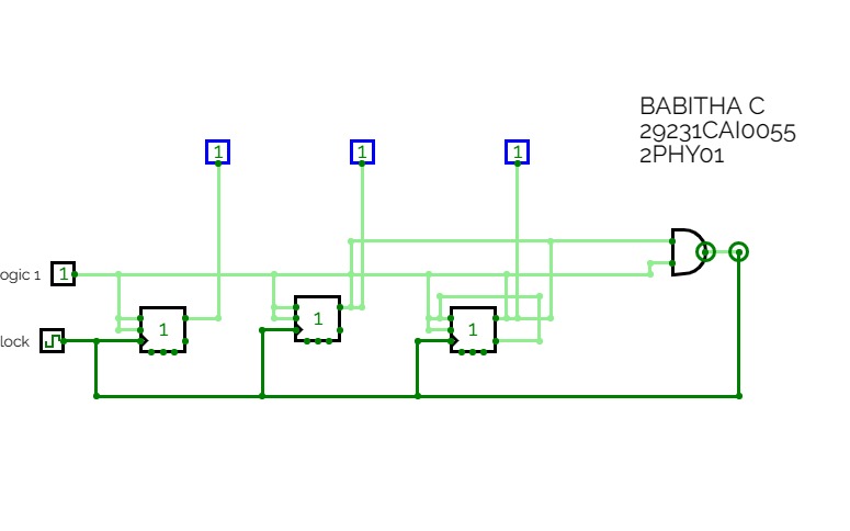
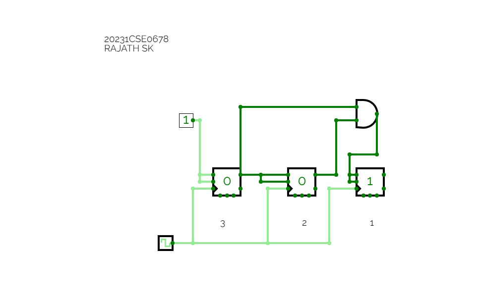
Circuitverse 3 Bit Synchronous Up Counter Using Jk Flip Flop I have to design 3 bit up synchronous counter using jk flip flops. the first one should count even numbers: 0 2 4 6 0. the second one should count odd numbers: 1 3 5 7 1. execution table for jk flip flop: first question: design a negative edge triggered synchronous counter with the form of operation: 0 2 4 6 0. my design:. This tutorial shows how to design a 3 bit synchronous down counter with jk flip flops. state table. it is clearly that the count down function has 8 states. in other words, the design is a mod 8 counter. Explore digital circuits online with circuitverse. with our easy to use simulator interface, you will be building circuits in no time. Successfully designed a 3 bit synchronous up down counter using jk flip flop in verilog. wrote the test bench for the same and verified the circuitry using some additional combinational logics. The paper discusses the design and implementation of a 3 bit counter using j k flip flops. it focuses on both synchronous and asynchronous counter configurations and highlights the use of k maps for deriving logic equations. Dive into the world of sequential logic circuits and digital circuit design as we explore step by step the construction of this efficient counter.
Comments are closed.