Solved Task 1 1 Construct Forward Biased And Reverse Chegg

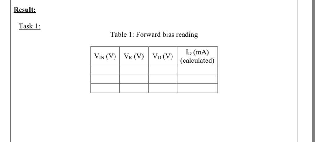
Solved Task 1 1 Construct Forward Biased And Reverse Chegg To get started on constructing the forward biased and reverse biased circuits, connect a power supply of 0 2v in series with a 1kΩ resistor and a diode, as shown in figure a. For each circuit, it identifies the operating region of the transistor (s) by determining whether the base emitter and base collector junctions are forward or reverse biased based on the given voltages. it also calculates current, voltage, and power values at the operating points of the transistors.

Solved Tasks 1 1 1 4 Is Already Solved But You Will Use Them Chegg Figure 1 shows the characteristics of an ideal diode under both forward and reverse bias. in forward bias the current increases exponentially, or nearly so, and in reverse bias the current is relatively constant and is equal to io. 1. draw the circuit diagram of a p n junction in forward and reverse bias. how are these circuits used to study the answered step by step solved by verified expert university of south africa. The led lights up when the signal line feeding into it is high (or 1). make all the necessary connections to implement this new feature, using logic gates if necessary. Adjust the applied voltage, e, so that the voltage v across the zener diode equals each value in table 1. for each value of v, measure the voltage across the resistor (to determine the forward current through the zener diode).

Solved 1 1 Chegg The led lights up when the signal line feeding into it is high (or 1). make all the necessary connections to implement this new feature, using logic gates if necessary. Adjust the applied voltage, e, so that the voltage v across the zener diode equals each value in table 1. for each value of v, measure the voltage across the resistor (to determine the forward current through the zener diode). In any transistor circuit, the base emitter junction must always be reversed biased and the collector bae junction must always be forward biased. to determine if a transistor is good or bad, a digital multimeter (dmm) or a transistor tester can be used. To determine whether each diode in figure 1 is forward biased or reverse biased and the voltage across each diode, we need to analyze each circuit individually. Step by step explanation step 1: (a) in multisim, the forward bias circuit is connected as depicted below. forward bias occurs when the battery's ve terminal is connected to the diode anode (or p type) in the manner depicted. The connection of an external battery, illustrated in fig. 1 5, is an example of reverse bias. the negative terminal attracts holes and concentrates them further to the left, while the positive terminal concentrates the electrons further to the right.

Solved 1 1 Chegg In any transistor circuit, the base emitter junction must always be reversed biased and the collector bae junction must always be forward biased. to determine if a transistor is good or bad, a digital multimeter (dmm) or a transistor tester can be used. To determine whether each diode in figure 1 is forward biased or reverse biased and the voltage across each diode, we need to analyze each circuit individually. Step by step explanation step 1: (a) in multisim, the forward bias circuit is connected as depicted below. forward bias occurs when the battery's ve terminal is connected to the diode anode (or p type) in the manner depicted. The connection of an external battery, illustrated in fig. 1 5, is an example of reverse bias. the negative terminal attracts holes and concentrates them further to the left, while the positive terminal concentrates the electrons further to the right.
Comments are closed.