Solved Section A Use Solidworks Part Modelling Assembly Chegg

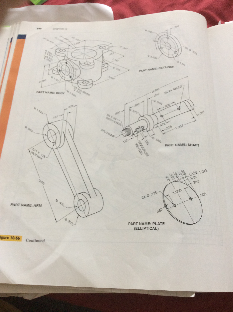
Solved Section A Use Solidworks Part Modelling Assembly Chegg Question: section a use solidworks part modelling, assembly modelling and drawing detailing to complete the following: question 1: multi purpose chair design challenge draw a multi purpose chair, the main function of a chair is to be able to seat down. Our expert help has broken down your problem into an easy to learn solution you can count on. question: a) create 3d solid models of each part in solidworks parts. save each part as solidworks part file (*.sldprt). b) create a 3d assembly and save it as a solidworks assembly part (*.sldasm).

Solved Section A Use Solidworks Part Modelling Assembly Chegg Our expert help has broken down your problem into an easy to learn solution you can count on. question: associate cswa full exam question 6 of 14 for 15 points: d11201: intermediate part step 1 (wheel) build this part in solidworks. Question: problem 1 using solidworks create the solid model from (engineering design and graphics with solidworks 2019) in chapter 4 chapter projects project 4 1 figure p4 90. the units are in mm s, make sure to use the appropriate unit system in solidworks. Question: 2.2 aligned section view use solidworks to model the 3 d part shown below and create the necessary views with an aligned section view in 3rd angle projections in a 2 d drawing. This is the fifth question of part modelling from the pdf of the cswa exam practice.pdf link: drive.google file d 1ra6t mis7ssotzhfwpdszctphzgzaef.

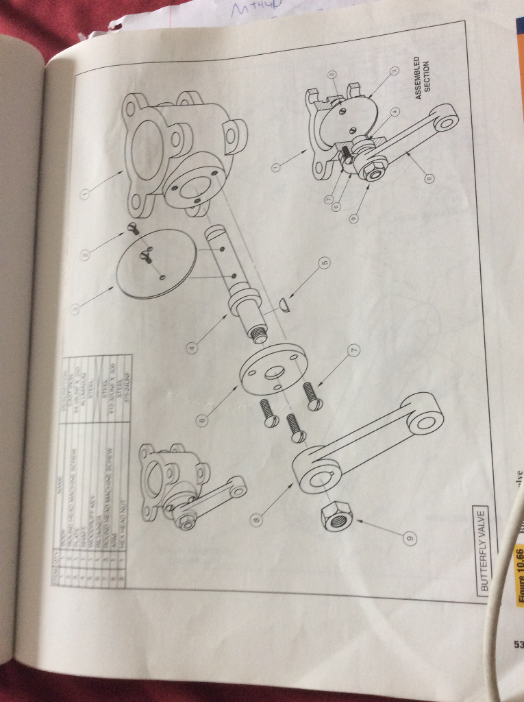
Using Solidworks For The Following Assembly Sketch Chegg Question: 2.2 aligned section view use solidworks to model the 3 d part shown below and create the necessary views with an aligned section view in 3rd angle projections in a 2 d drawing. This is the fifth question of part modelling from the pdf of the cswa exam practice.pdf link: drive.google file d 1ra6t mis7ssotzhfwpdszctphzgzaef. You are building an assembly with 2 components: a red block and a gray pivot. however, when you add a coincident mate between one of the faces of the red block and one of the faces of the gray pivot component, you end up with the assembly shown in the left image. Part modeling and assembly modeling questions that require you to build model should be correctly answered in 45 minutes or less. question 2 and question 3 should be correctly answered in 5 minutes or less. You first design and model parts; then insert them into an assembly and apply mates to position the parts. to modify the parts, you must edit them individually. Question: part ii 1. briefly describe how solid and surface modeling differ? 2. draw a circle of roughly 1 inch diameter. mark the radius and diameter of the circle using the proper engineering graphics drawing symbols 3. the on an assembly drawing lists the part names and indicates the number of each part in the assembly along with other.

Using Solidworks For The Following Assembly Sketch Chegg You are building an assembly with 2 components: a red block and a gray pivot. however, when you add a coincident mate between one of the faces of the red block and one of the faces of the gray pivot component, you end up with the assembly shown in the left image. Part modeling and assembly modeling questions that require you to build model should be correctly answered in 45 minutes or less. question 2 and question 3 should be correctly answered in 5 minutes or less. You first design and model parts; then insert them into an assembly and apply mates to position the parts. to modify the parts, you must edit them individually. Question: part ii 1. briefly describe how solid and surface modeling differ? 2. draw a circle of roughly 1 inch diameter. mark the radius and diameter of the circle using the proper engineering graphics drawing symbols 3. the on an assembly drawing lists the part names and indicates the number of each part in the assembly along with other.

Solved Part Chegg You first design and model parts; then insert them into an assembly and apply mates to position the parts. to modify the parts, you must edit them individually. Question: part ii 1. briefly describe how solid and surface modeling differ? 2. draw a circle of roughly 1 inch diameter. mark the radius and diameter of the circle using the proper engineering graphics drawing symbols 3. the on an assembly drawing lists the part names and indicates the number of each part in the assembly along with other.
Comments are closed.