Solved Rl Circuit Consider The Following Circuit With An Chegg

Solved Consider The Rl Circuit Of Figure 1 And Do The Chegg Our expert help has broken down your problem into an easy to learn solution you can count on. question: rl circuit consider the following circuit, with an ideal battery with an emf of e, three resistors, and an inductor. before t = 0, the switch has been open for a long time. In this tutorial, we explore rl circuits, key formulas, and solve practical problems. ideal for high school students, this guide offers clear explanations and step by step solutions.
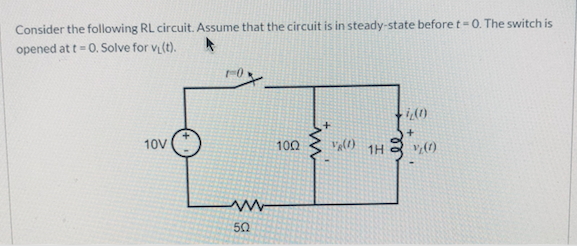
Solved Consider The Following Rl Circuit Assume That The Chegg The above figure shows a rl series circuit consisting of an inductor of inductance l connected in series with a resistor of resistance r . the switch, s , is closed at a time t = 0 and remains closed. "the format has forced me to think about what knowledge is needed by the student to solve a problem and present it concisely and understandably within the time constraint of the video. In summary, when the voltage applied to an inductor is changed, the current also changes, but the change in current lags the change in voltage in an rl circuit. in reactance, inductive and capacitive, we explore how an rl circuit behaves when a sinusoidal ac voltage is applied. First order circuit a circuit that can be simplified to a thévenin (or norton) equivalent connected to either a single equivalent inductor or capacitor. in ch7, the source is either none (natural response).
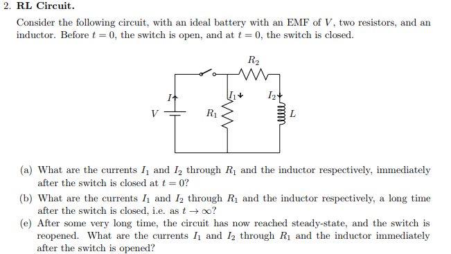
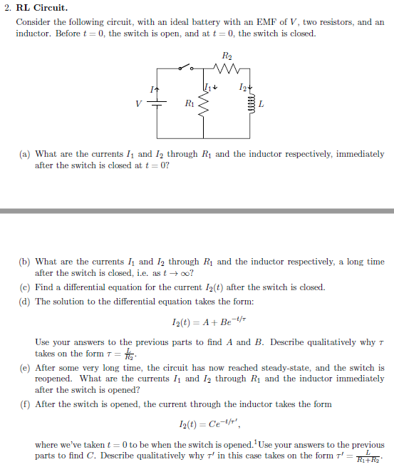
Solved 2 Rl Circuit Consider The Following Circuit With An Chegg In summary, when the voltage applied to an inductor is changed, the current also changes, but the change in current lags the change in voltage in an rl circuit. in reactance, inductive and capacitive, we explore how an rl circuit behaves when a sinusoidal ac voltage is applied. First order circuit a circuit that can be simplified to a thévenin (or norton) equivalent connected to either a single equivalent inductor or capacitor. in ch7, the source is either none (natural response). A circuit with resistance and self inductance is known as an rl circuit. figure \ (\pageindex {1a}\) shows an rl circuit consisting of a resistor, an inductor, a constant source of emf, and switches \ (s 1\) and \ (s 2\). In this tutorial we are going to perform a very detailed mathematical analysis of a rl circuit. by the end of the article the reader will be able to understand how the current response of an rl circuit is calculated and how the principle of superposition is applied in practice. Here’s the best way to solve it. consider the following rl circuit. assume that the circuit is in steady state before t 0. the switch is opened at t = 0. solve for vz (t). r0 20 10v 100 v: 1h 50. not the question you’re looking for? post any question and get expert help quickly. Solved: problem 1 (15 marks) consider a rl circuit shown in figure below as a system whose input is the applied voltage x (t) and output is the inductor voltage y (t).
Solved 2 Rl Circuit Consider The Following Circuit With An Chegg A circuit with resistance and self inductance is known as an rl circuit. figure \ (\pageindex {1a}\) shows an rl circuit consisting of a resistor, an inductor, a constant source of emf, and switches \ (s 1\) and \ (s 2\). In this tutorial we are going to perform a very detailed mathematical analysis of a rl circuit. by the end of the article the reader will be able to understand how the current response of an rl circuit is calculated and how the principle of superposition is applied in practice. Here’s the best way to solve it. consider the following rl circuit. assume that the circuit is in steady state before t 0. the switch is opened at t = 0. solve for vz (t). r0 20 10v 100 v: 1h 50. not the question you’re looking for? post any question and get expert help quickly. Solved: problem 1 (15 marks) consider a rl circuit shown in figure below as a system whose input is the applied voltage x (t) and output is the inductor voltage y (t).
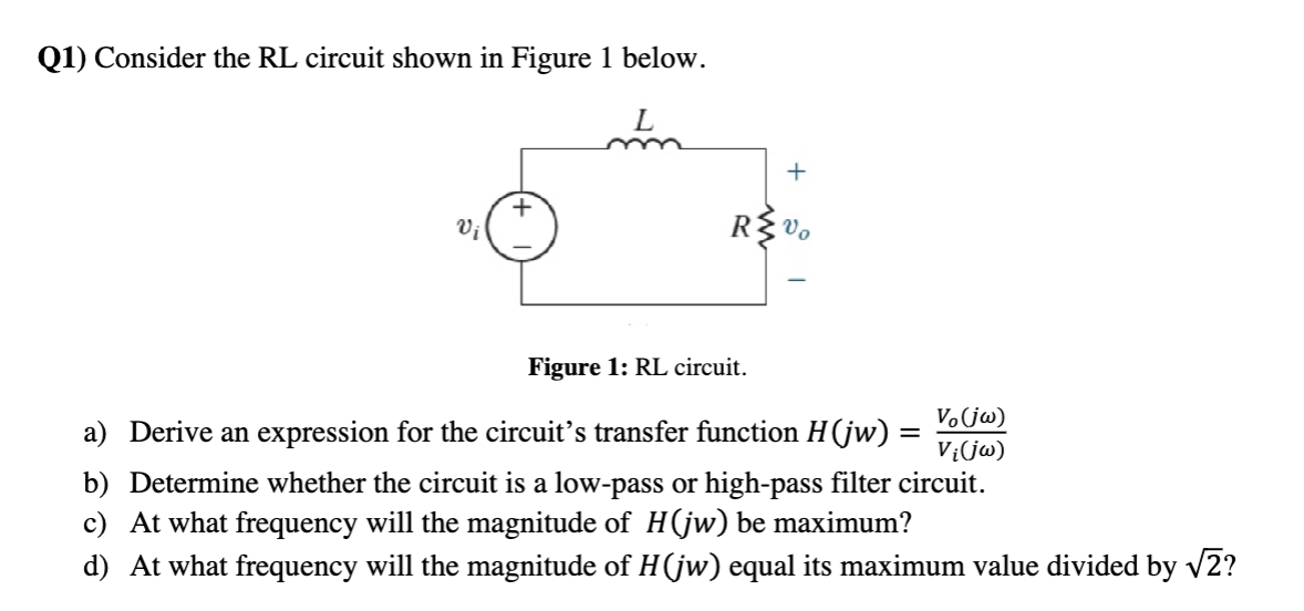
Solved Q1 Consider The Rl Circuit Shown In Figure 1 Below Chegg Here’s the best way to solve it. consider the following rl circuit. assume that the circuit is in steady state before t 0. the switch is opened at t = 0. solve for vz (t). r0 20 10v 100 v: 1h 50. not the question you’re looking for? post any question and get expert help quickly. Solved: problem 1 (15 marks) consider a rl circuit shown in figure below as a system whose input is the applied voltage x (t) and output is the inductor voltage y (t).
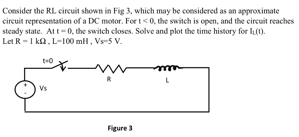
Solved Consider The Rl Circuit Shown In Fig 3 Which May Be Chegg
Comments are closed.