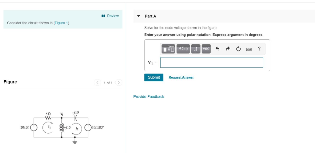
Solved Review Part A Consider The Circuit Shown In Figure Chegg

Solved Review Part A Consider The Circuit Shown In Figure Chegg Review part a consider the circuit shown in (figure 1). find the current through each resistor. figure 1 of 1 enter your answers in amperes separated by commas. Consider the circuit shown in (figure 1). what is the potential difference across the 10Ω resistor? what is the potential difference across the 20Ω resistor?.

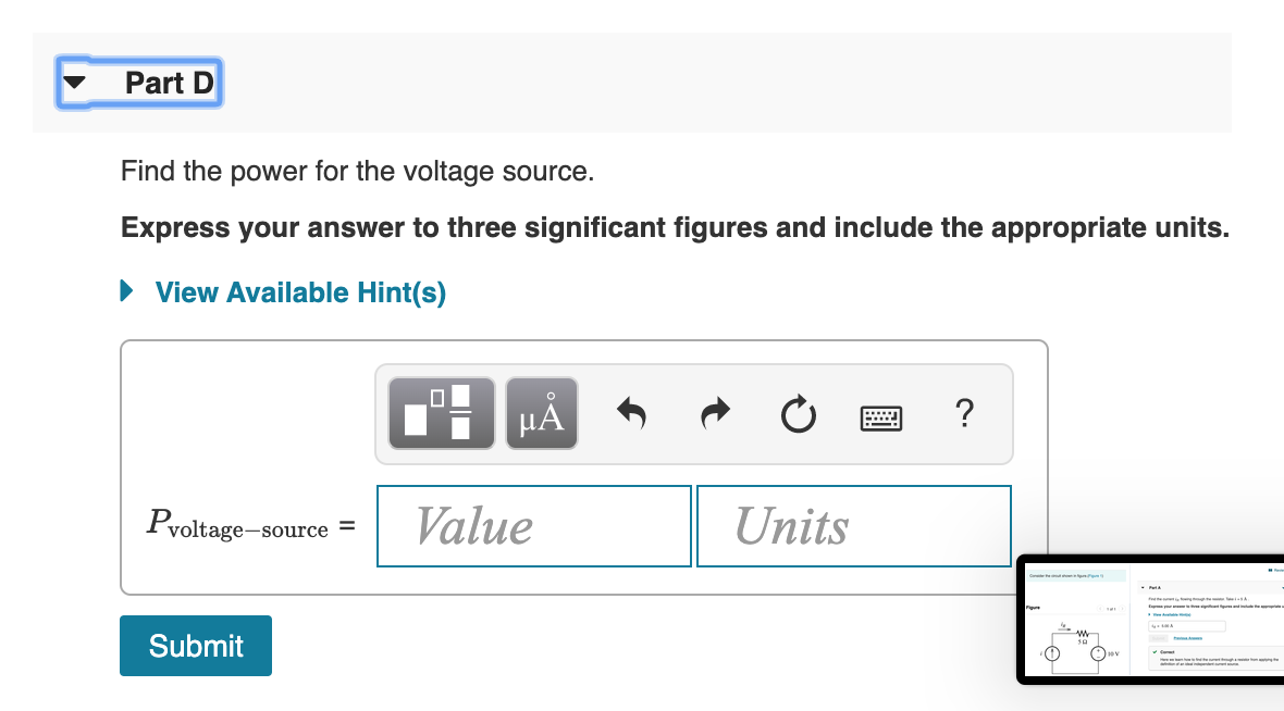
Solved Review Consider The Circuit Shown In Figure Figure Chegg To solve this problem, we'll need to analyze the circuit using the mesh current method. we'll determine the currents in each loop (mesh) and then calculate the power developed and dissipated in the circuit. Part a consider the circuit shown in (figure 1). suppose that i, = 8a. find 21 . express your answer to three significant figures and include the appropriate units. 21 = value units submit request answer part b find v. express your answer to three significant figures and include the appropriate units. ? v = value show more show more. In an electric circuit, the maximum power transferred to load resistance is 2Ω is 50 w. if now, the load resistance is changed to 8Ω, what will be the power transferred to the load?. Consider the circuit shown in figure 1. suppose that = 32. part a: determine the power for source a. express your answer to three significant figures and include the appropriate units. enter a positive value if the source is absorbing energy and a negative value if the source is delivering energy.

Solved Part A Consider The Circuit Shown In The Figure Chegg In an electric circuit, the maximum power transferred to load resistance is 2Ω is 50 w. if now, the load resistance is changed to 8Ω, what will be the power transferred to the load?. Consider the circuit shown in figure 1. suppose that = 32. part a: determine the power for source a. express your answer to three significant figures and include the appropriate units. enter a positive value if the source is absorbing energy and a negative value if the source is delivering energy. . v part a consider the circuit shown in (figure 1). suppose that v1 = 8 v and v2 = 3 v. use the mesh current answered step by step solved by verified expert university of washington. Element a. p 2.2 5 the circuit shown in figure p 2.2 5 consists of a current source, a resistor, and element a. Suppose that r1 25 r determine the closed loop voltage gain of the circuit shown in (figure 1), assuming an ideal op amp. express your answer to three significant figures. Consider the circuit shown in (figure 1). assume i = 0.88 a. what is the value of resistor r?.
Comments are closed.