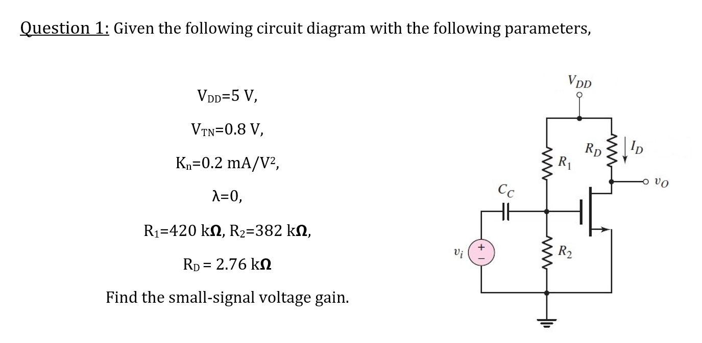
Solved Question 1 Given The Following Circuit With The Chegg

Solved Question 1 Given The Following Circuit Diagram With Chegg There are 3 steps to solve this one. 1. given the following circuit, calculate the current through resistor r, (i3 = ?). please use the practical model for the diode. 2. following figure shows a full wave rectifier circuit that uses a center tapped transformer. In the circuit below, the switch has been in the closed position for a long time. before the switch is opened, the voltage across the inductor is zero (vl = ldi dt = 0), i.e. the 1 kohm resistor is shorted out by the inductor.

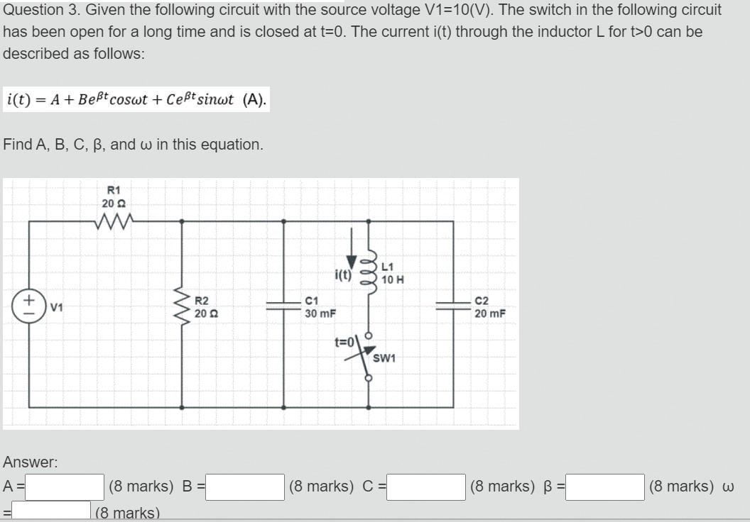
Solved Question 3 Given The Following Circuit With The Chegg Study with quizlet and memorize flashcards containing terms like ohm's law can only be applied to series and parallel circuits; to solve for combination circuits, kirchhoff's law must be applied. Solution for assignment 1 problem (20 pts.) a) given for the electrical system: [circuit diagram with a voltage source e (t), capacitor c, inductor l, and resistor r in a series paralle. Question 1: for the electrical circuit given in the following figure 1 determine the following: there are 3 steps to solve this one. let' not the question you’re looking for? post any question and get expert help quickly. = 1. a pn junction has the doping concentrations o chegg 2 free download as pdf file (.pdf), text file (.txt) or read online for free.

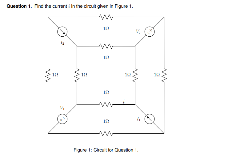
Solved Question 1 Find The Current I In The Circuit Given Chegg Question 1: for the electrical circuit given in the following figure 1 determine the following: there are 3 steps to solve this one. let' not the question you’re looking for? post any question and get expert help quickly. = 1. a pn junction has the doping concentrations o chegg 2 free download as pdf file (.pdf), text file (.txt) or read online for free. The simplest electric circuit shown in figure 1 contains an electromotive force (usually a battery or generator) that produces a voltage of e (t) volts (v) and a current of i (t) amperes (a) at time t. Consider the circuit below with the mesh currents. but, we need one more equation, so we use the constraint equation –i3 i4 = 10. this now gives us three equations with three unknows. we can now. In an electric circuit, the maximum power transferred to load resistance is 2Ω is 50 w. if now, the load resistance is changed to 8Ω, what will be the power transferred to the load?. (a) develop a order differential equation that will allow you to solve for vc(t). (b) determine the 2n order characteristic equation in terms of r, l, and c. (c) determine r and c so that = 5 rad sec and = 0.5 .

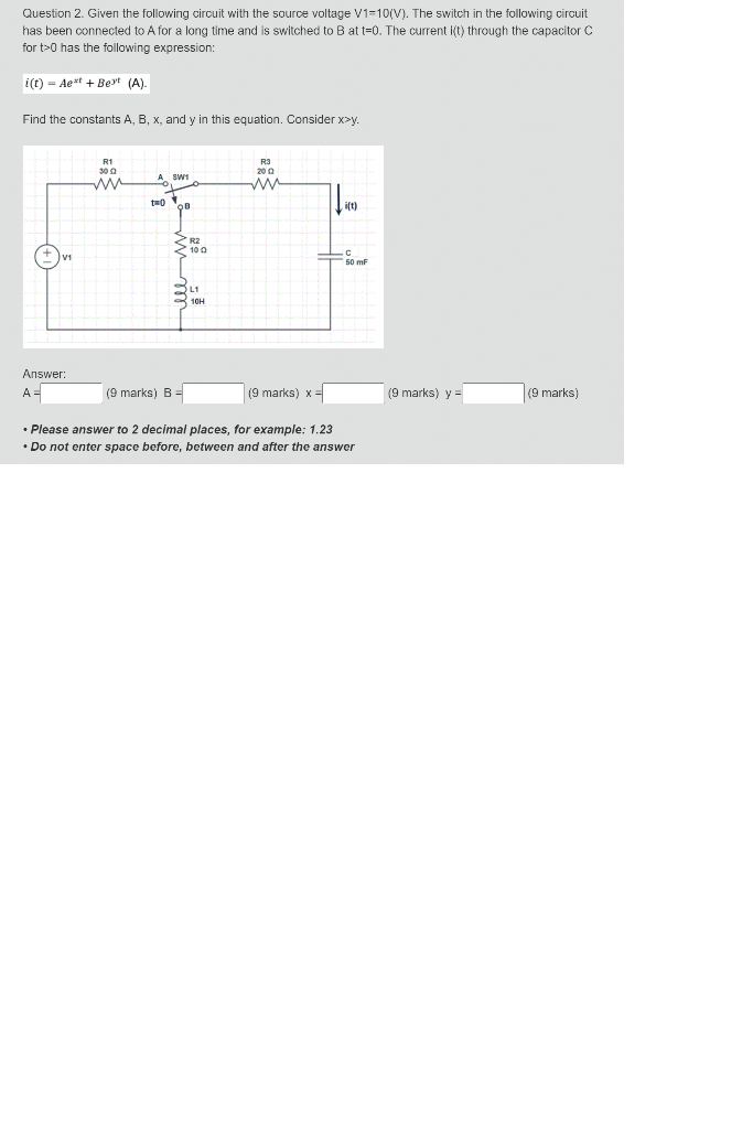
Solved Question 2 Given The Following Circuit With The Chegg The simplest electric circuit shown in figure 1 contains an electromotive force (usually a battery or generator) that produces a voltage of e (t) volts (v) and a current of i (t) amperes (a) at time t. Consider the circuit below with the mesh currents. but, we need one more equation, so we use the constraint equation –i3 i4 = 10. this now gives us three equations with three unknows. we can now. In an electric circuit, the maximum power transferred to load resistance is 2Ω is 50 w. if now, the load resistance is changed to 8Ω, what will be the power transferred to the load?. (a) develop a order differential equation that will allow you to solve for vc(t). (b) determine the 2n order characteristic equation in terms of r, l, and c. (c) determine r and c so that = 5 rad sec and = 0.5 .

Solved Question 3 Given The Following Circuit With The Chegg In an electric circuit, the maximum power transferred to load resistance is 2Ω is 50 w. if now, the load resistance is changed to 8Ω, what will be the power transferred to the load?. (a) develop a order differential equation that will allow you to solve for vc(t). (b) determine the 2n order characteristic equation in terms of r, l, and c. (c) determine r and c so that = 5 rad sec and = 0.5 .
Comments are closed.