Solved Q2 Design A Synchronous Counter Using Jkff Which Chegg

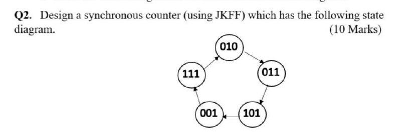
Solved Q2 Design A Synchronous Counter Using Jkff Which Chegg Q2. design a synchronous counter (using jkff) which has the following state diagram. (10 marks) 010 111 (011 001 101 your solution’s ready to go! our expert help has broken down your problem into an easy to learn solution you can count on. Implement and design a synchronous counter for given sequence using jk flip flop counter using jk flip #mathsolympiadpreparation more.

Circuit Design 2 Bit Synchronous Using Jkff Tinkercad Several methods exist for designing counters that follow arbitrary sequences, in this exercise, you will be introduced to the design a synchronous counter using j k flip flops. Our expert help has broken down your problem into an easy to learn solution you can count on. question: q2) design a mod 8 synchronous counter using j k flip flops with a 50 mhz clock input as follows: a) calculate the number of flip flops required. b) draw the counter circuit diagram. A synchronous counter using two j – k flip flops that goes through the sequence of states: q 1 q 2 = 00 → 10 → 01 → 11 → 00 …. is required. to achieve this, the inputs to the flip flops are. option 2 : j 1 = 1, k 1 = 1; j 2 = q 1, k 2 = q 1. by using excitation table of jk flip flop. The subject code is csen1051. i would like to explain the concepts of digital logic circuits to the students using around 10 minute videos.

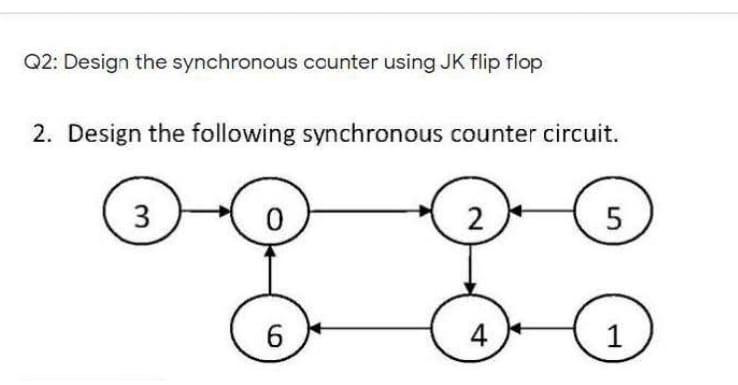
Solved Q2 Design The Synchronous Counter Using Jk Flip Flop Chegg A synchronous counter using two j – k flip flops that goes through the sequence of states: q 1 q 2 = 00 → 10 → 01 → 11 → 00 …. is required. to achieve this, the inputs to the flip flops are. option 2 : j 1 = 1, k 1 = 1; j 2 = q 1, k 2 = q 1. by using excitation table of jk flip flop. The subject code is csen1051. i would like to explain the concepts of digital logic circuits to the students using around 10 minute videos. The steps to design a synchronous counter using jk flip flops are: 1. description. describe a general sequential circuit in terms of its basic parts and its input and outputs. design a 2 bit up down counter with an input d which determines the up down function. Question: 3 bit synchronous counter jkff. (1=> 2=> 3 =>4=> 5=> 6=> 7=> 0) will be designed according to this order. the counter circuit should be designed with jk ff. the outputs of the designed synchronous counter will be expressed as q2, q1 and q0. The design steps are somewhat similar for both synchronous counter and asynchronous counter but differ slightly. follow the below given steps to design the synchronous counter. Our expert help has broken down your problem into an easy to learn solution you can count on. question: 1) design a synchronous counter using jkff. it is a down counter, mod 6. 1) design a synchronous counter using jkff. it is a down counter, mod 6. here’s the best way to solve it. not the question you’re looking for?.
Comments are closed.