Solved Problem 4 Dc Power Flow Method Determine The Power Flows On

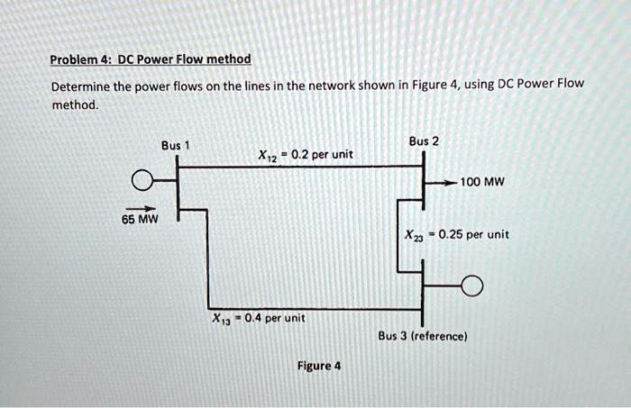
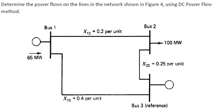
Solved Problem 4 Dc Power Flow Method Determine The Power Flows On Problem 4: dc power flow method determine the power flows on the lines in the network shown in figure 4, using dc power flow method. figure 4. your solution’s ready to go! our expert help has broken down your problem into an easy to learn solution you can count on. However, the problem statement requires us to compute the power flows on the lines (this is usually the information needed by operational and planning engineers as they study the power system).

Solved Determine The Power Flows On The Lines In The Network Shown In Calculate complex, real, and reactive power injected into each bus this can be done using 101 䠞 < and vectors and element by element multiplication (the .* operator. Solved: problem 4: dc power flow method determine the power flows on the lines in the network shown in figure 4, using dc power flow method. bus 1 bus 2 x12 = 0.2 per unit 100 mw 65 mw x23 = 0.25 per unit x = 0.4 per unit bus 3 (reference) figure 4 we're recalculating the answer now 1%. Solve for the current, load voltage and load power in the previous circuit, assuming a 3f power base of 300 mva, and line to line voltage bases of 13.8 kv, 138 kv and 27.6 kv (square root of 3 larger than the 1f example voltages). Your solution’s ready to go! our expert help has broken down your problem into an easy to learn solution you can count on. see answer.

The Dc Power Flow Equations Pdf Trigonometric Functions Ac Power Solve for the current, load voltage and load power in the previous circuit, assuming a 3f power base of 300 mva, and line to line voltage bases of 13.8 kv, 138 kv and 27.6 kv (square root of 3 larger than the 1f example voltages). Your solution’s ready to go! our expert help has broken down your problem into an easy to learn solution you can count on. see answer. Identify the elements for the state vector x for this problem. solution: =[ express h(x), the measurements as functions of the states using ac power flow expressions. The power flow loop is where the traditional power flow matrix equations are solved. there are several common and advanced solution options which affect this loop. Determining which bus serves as the slack bus in power flow analysis is often a design decision because rarely does a single node satisfy the network power imbalance in reality.1. Draw an impedance diagram for the electric power system shown in figure, showing all impedances in per unit on a 100 mva base. choose 22 kv as the voltage base for the generator.

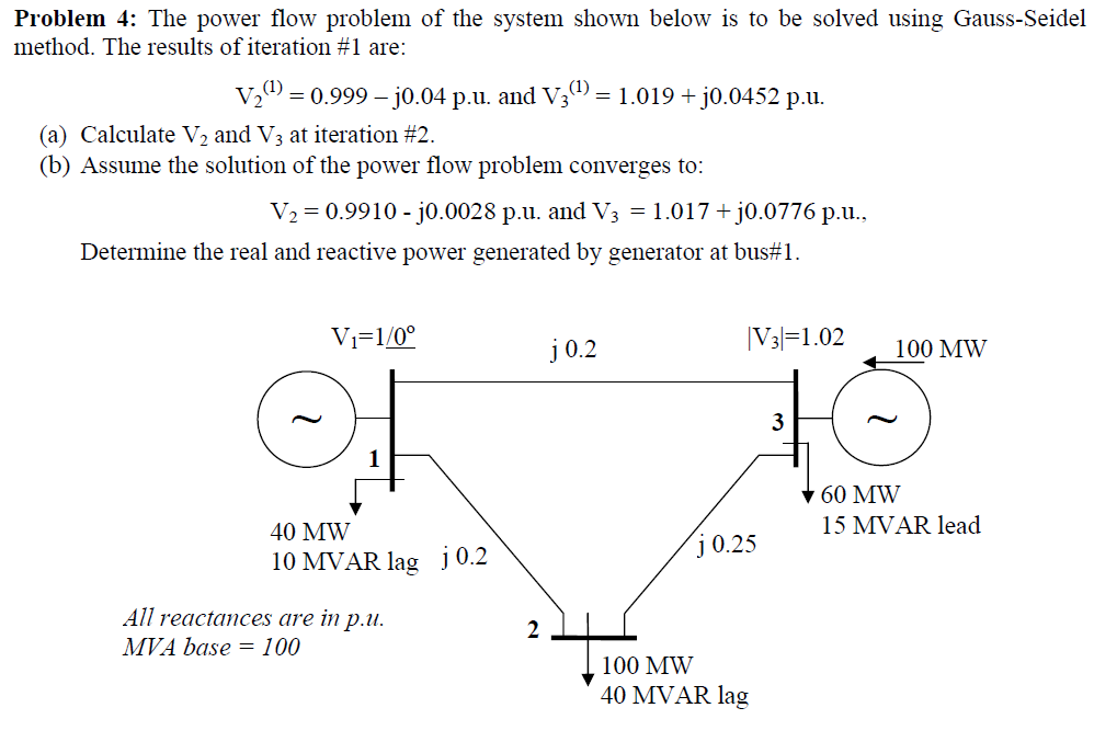
Solved Problem 4 The Power Flow Problem Of The System Shown Chegg Identify the elements for the state vector x for this problem. solution: =[ express h(x), the measurements as functions of the states using ac power flow expressions. The power flow loop is where the traditional power flow matrix equations are solved. there are several common and advanced solution options which affect this loop. Determining which bus serves as the slack bus in power flow analysis is often a design decision because rarely does a single node satisfy the network power imbalance in reality.1. Draw an impedance diagram for the electric power system shown in figure, showing all impedances in per unit on a 100 mva base. choose 22 kv as the voltage base for the generator.

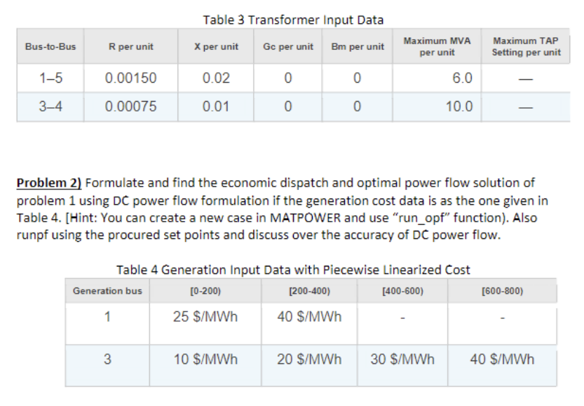
Problem 1 Determine The Dc Power Flow Solution For Chegg Determining which bus serves as the slack bus in power flow analysis is often a design decision because rarely does a single node satisfy the network power imbalance in reality.1. Draw an impedance diagram for the electric power system shown in figure, showing all impedances in per unit on a 100 mva base. choose 22 kv as the voltage base for the generator.

Solved Problem 1 Determine The Dc Power Flow Solution For Chegg
Comments are closed.