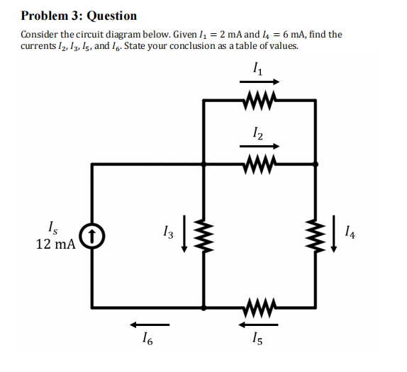
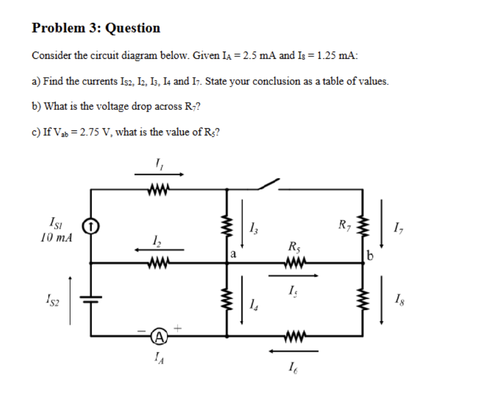
Solved Problem 3 Question Consider The Circuit Diagram Chegg

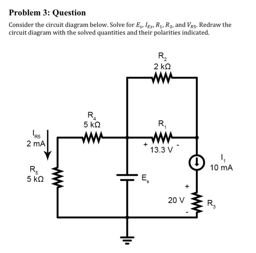
Solved Problem 2 Question Consider The Circuit Diagram Chegg Problem 3: question consider the circuit diagram below. solve for the current values and directions through r1 and r4, and the voltage drop across r3 using mesh analysis. you may consider redrawing the circuit at the end of your analysis to better demonstrate polarities. The difference between no.2 (diode) and no.3 (diode) is that they may be oriented differently in the circuit, affecting the direction of current flow. diodes allow current to flow in one direction only, from the anode to the cathode.

Solved Problem 3 Question Consider The Circuit Diagram Chegg Consider the circuit diagram shown below. assume all circuit elements are ideal.the end goal of this problem is to determine the charge on and the voltage across each capacitor.what is the charge on capacitor 1?. Solved s consider the circuit in figure 2 for questions chegg com 8 systematic methods of circuit analysis foundations electromagnetic compatibility with practical applications book. The answer does not seem correct. can you verify the solution again for problem 3 (c) ? tutor. Consider the circuit shown in the figure below. [15 points] (a) obtain an expression for the apparent power, s, by the sending end voltage source, your answer should only contain vs, vr, δ, x, and b. [5 points] (b) obtain an expression for the real power generated by the sending end voltage source, vs.

Solved Problem 3 Question Consider The Circuit Diagram Chegg The answer does not seem correct. can you verify the solution again for problem 3 (c) ? tutor. Consider the circuit shown in the figure below. [15 points] (a) obtain an expression for the apparent power, s, by the sending end voltage source, your answer should only contain vs, vr, δ, x, and b. [5 points] (b) obtain an expression for the real power generated by the sending end voltage source, vs. Consider a silicon sample maintained at 300k under equilibrium conditions, uniformly doped with 1*1016 cm 3 phosphorus atoms. the surface region of the sample is additionally doped uniformly with 5*1016 cm 3 boron atoms, to a depth of 1 microm, as shown in the figure below. Our expert help has broken down your problem into an easy to learn solution you can count on. question: problem 3: question consider the circuit diagram below. the circuit supplies power to the unknown resistive load, l. determine the thevenin equivalent circuit for the supply circuit. Consider the electrical circuit shown in figure 3–37. obtain the transfer function e o (s) e i (s) by use of the block diagram approach. Consider the circuit shown in the diagram below, for r1 = 5 Ω, r2 = 8 Ω, r3 = 8 Ω, r4 = 8 Ω, and v0 = 8.0 v. calculate the current through r4. i guess i'm kind of lost with where to begin. the examples in class were a little more simplified but i'll say what my thought process is to solving it.

Solved Problem 3 Questionconsider The Circuit Diagram Chegg Consider a silicon sample maintained at 300k under equilibrium conditions, uniformly doped with 1*1016 cm 3 phosphorus atoms. the surface region of the sample is additionally doped uniformly with 5*1016 cm 3 boron atoms, to a depth of 1 microm, as shown in the figure below. Our expert help has broken down your problem into an easy to learn solution you can count on. question: problem 3: question consider the circuit diagram below. the circuit supplies power to the unknown resistive load, l. determine the thevenin equivalent circuit for the supply circuit. Consider the electrical circuit shown in figure 3–37. obtain the transfer function e o (s) e i (s) by use of the block diagram approach. Consider the circuit shown in the diagram below, for r1 = 5 Ω, r2 = 8 Ω, r3 = 8 Ω, r4 = 8 Ω, and v0 = 8.0 v. calculate the current through r4. i guess i'm kind of lost with where to begin. the examples in class were a little more simplified but i'll say what my thought process is to solving it.

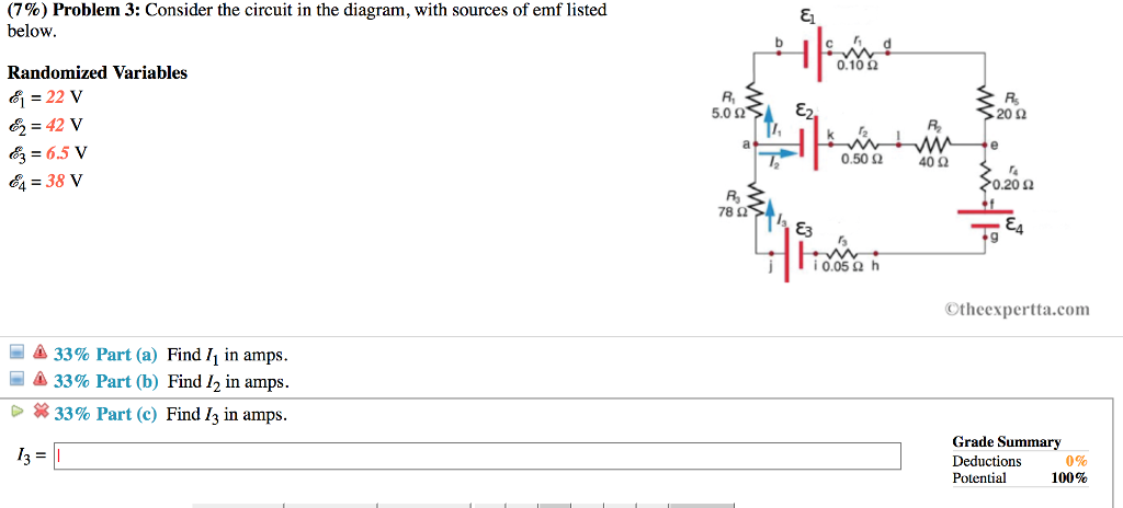
Solved 7 Problem 3 Consider The Circuit In The Diagram Chegg Consider the electrical circuit shown in figure 3–37. obtain the transfer function e o (s) e i (s) by use of the block diagram approach. Consider the circuit shown in the diagram below, for r1 = 5 Ω, r2 = 8 Ω, r3 = 8 Ω, r4 = 8 Ω, and v0 = 8.0 v. calculate the current through r4. i guess i'm kind of lost with where to begin. the examples in class were a little more simplified but i'll say what my thought process is to solving it.
Comments are closed.