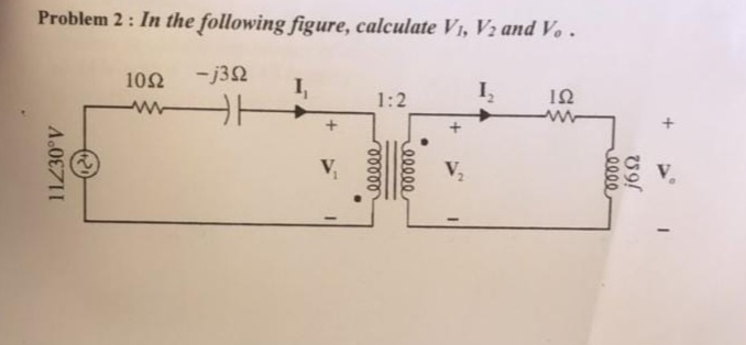
Solved Problem 2 In The Following Figure Calculate V1 V2 Chegg

Solved Problem 2 In The Following Figure Calculate V1 V2 Chegg Problem 2 : in the following figure, calculate v1,v2 and vo. your solution’s ready to go! our expert help has broken down your problem into an easy to learn solution you can count on. question: problem 2 : in the following figure, calculate v1,v2 and vo. there’s just one step to solve this. Determine v1 and v2 in the circuit of fig. | electrical engineering electrical engineering 74.4k subscribers subscribe.

Solved Problem 2 In The Following Figure Calculate Chegg Consider a circuit shown below in which r 1 and r 2 are two resistance, v 1, v 2 are two voltage source which causes current (i) flow in the loop. the sign of voltage drop across the passive element is such a way that the current entering from the positive terminal. Question (2) (10 mark) calculate the node voltages v1, v2, and v3 in the circuit shown in the next figure. 🤔 not the exact question you're looking for? kirchhoff's current law (kcl) states that the sum of currents entering a node equals the sum of currents leaving the node. Find v1 and v2 in the circuit in fig. p3.5 using nodal analysis. we will label two nodes to perform nodal analysis on this circuit as follows:. Calculate the current flowing through the load resistor r l due to a single source. repeat steps 2 and 3 for all other sources in the circuit. to find the total current through the load resistor, perform an algebraic sum of the currents produced by each independent source.

Calculate V1 ï And V2 ï In The Following Figure 5 Chegg Find v1 and v2 in the circuit in fig. p3.5 using nodal analysis. we will label two nodes to perform nodal analysis on this circuit as follows:. Calculate the current flowing through the load resistor r l due to a single source. repeat steps 2 and 3 for all other sources in the circuit. to find the total current through the load resistor, perform an algebraic sum of the currents produced by each independent source. There are two branches (left and middle right and far right) where the 10ma current source will split. all branches will have the same voltage v 2 across them. write out the equations with three branch currents (i 1, i 2, i 3) will sum to 10ma and solve. Once we determine the values for the node voltages v1, v2, v3 we will be able to completely characterize this circuit. so let’s go on to calculate the node voltages by applying kcl at the designated nodes. Your solution’s ready to go! our expert help has broken down your problem into an easy to learn solution you can count on. see answer. To calculate the voltages v1, v2, and v3 in the circuit with given values for vw, vx, vy, and vz, apply kirchhoff's voltage law (kvl), which states that the sum of voltages in a closed loop equals zero. begin by marking the known voltage values on the circuit diagram to visualize the relationships.

Solved In The Following Figure V1 2v V2 5v Calculate V0 Chegg There are two branches (left and middle right and far right) where the 10ma current source will split. all branches will have the same voltage v 2 across them. write out the equations with three branch currents (i 1, i 2, i 3) will sum to 10ma and solve. Once we determine the values for the node voltages v1, v2, v3 we will be able to completely characterize this circuit. so let’s go on to calculate the node voltages by applying kcl at the designated nodes. Your solution’s ready to go! our expert help has broken down your problem into an easy to learn solution you can count on. see answer. To calculate the voltages v1, v2, and v3 in the circuit with given values for vw, vx, vy, and vz, apply kirchhoff's voltage law (kvl), which states that the sum of voltages in a closed loop equals zero. begin by marking the known voltage values on the circuit diagram to visualize the relationships.

Solved In The Circuit In Figure 2 ï Calculate V1 V2 Figure 2 Chegg Your solution’s ready to go! our expert help has broken down your problem into an easy to learn solution you can count on. see answer. To calculate the voltages v1, v2, and v3 in the circuit with given values for vw, vx, vy, and vz, apply kirchhoff's voltage law (kvl), which states that the sum of voltages in a closed loop equals zero. begin by marking the known voltage values on the circuit diagram to visualize the relationships.

Solved Question 2 A Based On Figure 2 Calculate The Chegg
Comments are closed.