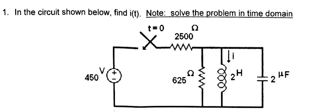
Solved Problem 1 In The Circuit Shown Below Find Chegg

Solved Problem 1 In The Circuit Shown Below Find Chegg Our expert help has broken down your problem into an easy to learn solution you can count on. there are 2 steps to solve this one. not the question you’re looking for? post any question and get expert help quickly. Consider the circuit shown in the figure below. [15 points] (a) obtain an expression for the apparent power, s, by the sending end voltage source, your answer should only contain vs, vr, δ, x, and b. [5 points] (b) obtain an expression for the real power generated by the sending end voltage source, vs.

Solved In The Circuit Shown Below Find I T Chegg In the circuit below, the switch has been in the closed position for a long time. before the switch is opened, the voltage across the inductor is zero (vl = ldi dt = 0), i.e. the 1 kohm resistor is shorted out by the inductor. Step by step solution using mesh analysis to find current i0 in a circuit. electrical engineering problem. Part a consider the circuit shown in (figure 1). suppose that i, = 8a. find 21 . express your answer to three significant figures and include the appropriate units. 21 = value units submit request answer part b find v. express your answer to three significant figures and include the appropriate units. ? v = value show more show more. Consider the circuit below with the mesh currents. but, we need one more equation, so we use the constraint equation –i3 i4 = 10. this now gives us three equations with three unknows. we can.

Solved Problem 1 In The Circuit Shown Below Find Vs Chegg Part a consider the circuit shown in (figure 1). suppose that i, = 8a. find 21 . express your answer to three significant figures and include the appropriate units. 21 = value units submit request answer part b find v. express your answer to three significant figures and include the appropriate units. ? v = value show more show more. Consider the circuit below with the mesh currents. but, we need one more equation, so we use the constraint equation –i3 i4 = 10. this now gives us three equations with three unknows. we can. The simplest electric circuit shown in figure 1 contains an electromotive force (usually a battery or generator) that produces a voltage of e (t) volts (v) and a current of i (t) amperes (a) at time t. Task 1 (of 3) consider the circuit shown below. find the equivalent circuit containing only one voltage source and one resistor to address prompts (a) (c). (a) what's the resistance of the single resistor in the equivalent circuit? (b) what's the magnitude of the current in the equivalent circuit? (c) what's the power dissipated by the resistor?. For the circuit shown below, find (a) the total power dissipated in the circuit and (b) thepower dissipated in the 45Ω resistor. your solution’s ready to go! our expert help has broken down your problem into an easy to learn solution you can count on. question: problem 1. The switch has been open for a very long time and is closed at t = o. (a) develop a 2n order differential equation that will allow you to solve for vc(t). (b) determine the 2 n order characteristic equation in terms of r, l, and c. (c) determine r and c so that = 5 rad sec and = 0.5 .

Solved From Problem 8 1 A For The Circuit Shown Below Chegg The simplest electric circuit shown in figure 1 contains an electromotive force (usually a battery or generator) that produces a voltage of e (t) volts (v) and a current of i (t) amperes (a) at time t. Task 1 (of 3) consider the circuit shown below. find the equivalent circuit containing only one voltage source and one resistor to address prompts (a) (c). (a) what's the resistance of the single resistor in the equivalent circuit? (b) what's the magnitude of the current in the equivalent circuit? (c) what's the power dissipated by the resistor?. For the circuit shown below, find (a) the total power dissipated in the circuit and (b) thepower dissipated in the 45Ω resistor. your solution’s ready to go! our expert help has broken down your problem into an easy to learn solution you can count on. question: problem 1. The switch has been open for a very long time and is closed at t = o. (a) develop a 2n order differential equation that will allow you to solve for vc(t). (b) determine the 2 n order characteristic equation in terms of r, l, and c. (c) determine r and c so that = 5 rad sec and = 0.5 .

Solved Problem 1 In The Circuit Shown Below Find V1 7 5 Chegg For the circuit shown below, find (a) the total power dissipated in the circuit and (b) thepower dissipated in the 45Ω resistor. your solution’s ready to go! our expert help has broken down your problem into an easy to learn solution you can count on. question: problem 1. The switch has been open for a very long time and is closed at t = o. (a) develop a 2n order differential equation that will allow you to solve for vc(t). (b) determine the 2 n order characteristic equation in terms of r, l, and c. (c) determine r and c so that = 5 rad sec and = 0.5 .
Comments are closed.