Solved In This Question You Will Find Three Input Pins And Chegg

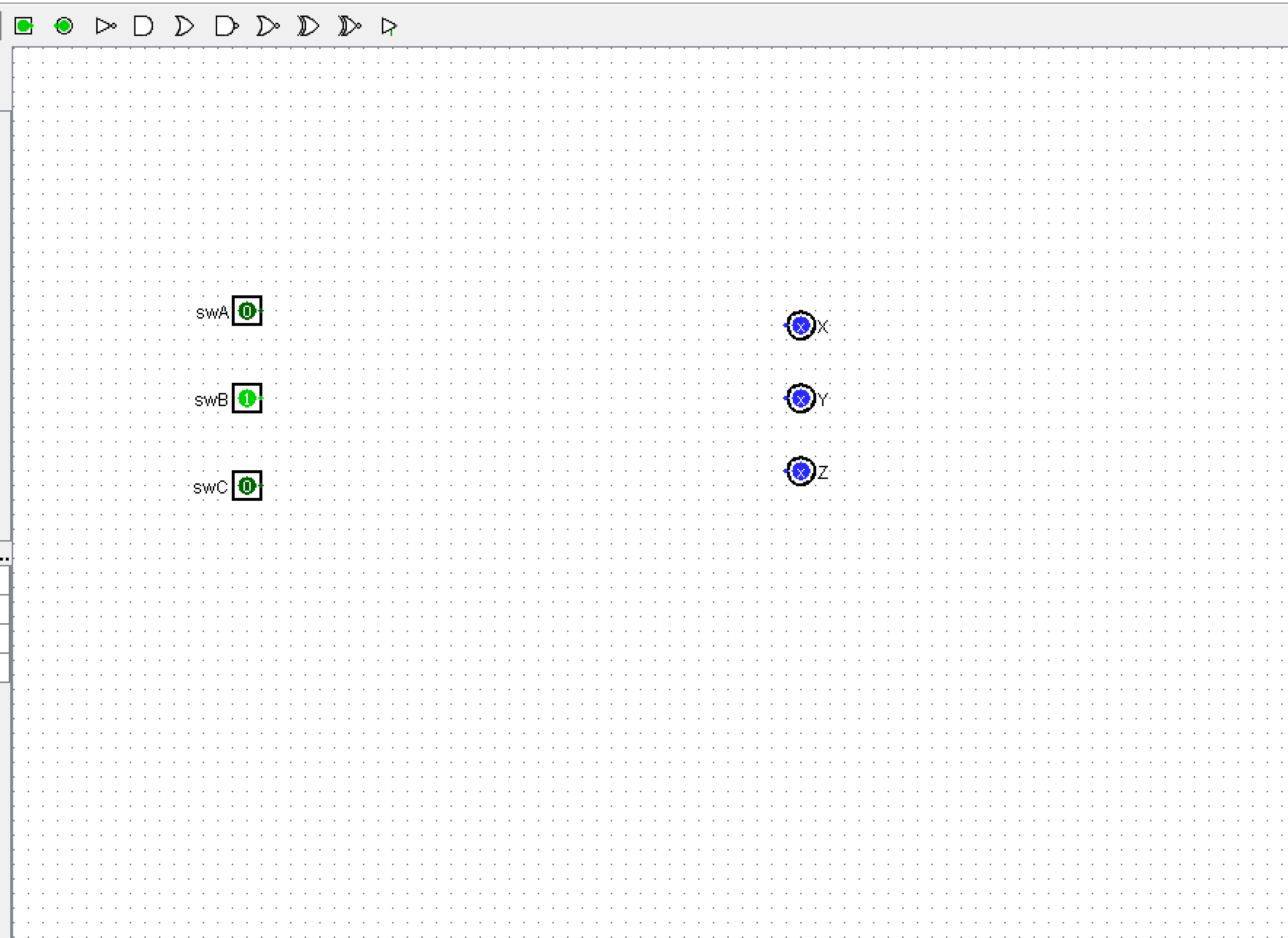
Solved In This Question You Will Find Three Input Pins And Chegg In this question, you will find three input pins and three output pins which are representations of the switches and leds found in the problem 01 subcircuit (attached below). This will help you determine the connections between the full adders and the input output pins. for a more detailed implementation, you can refer to the specific logic gates and their connections required for each full adder.

Solved In This Question You Will Find Three Input Pins And Chegg I clear students doubts by giving handwritten solution and improve their problem solving skills in chegg. working on gradeup school app i solved questions posted by high school and college students. Question 2 in this question, you will design a logic circuit for a 3 bit “prime number detector” circuit. the circuit has three inputs for the 3 bits of a 3 bit number p= p2p1p0 , and has one output zsuch that z = 1 if p is a prime number (i.e. if p = 1, 2, 3, 5, 7 in decimal) and z = 0 if p is not a prime number (i.e. if p = 0, 4, 6 in decimal). a) draw up the truth table for zas a. Take the ttl logic gates (digital circuits) worksheet. these questions & answers will help you master the topic!. On boards with a limited number of adc pins, like the arduino uno, you can use multiplexing to read multiple analog sensors. by switching the input channels, you can read from different analog sources sequentially.

Solved In This Question You Will Find Three Input Pins And Chegg Take the ttl logic gates (digital circuits) worksheet. these questions & answers will help you master the topic!. On boards with a limited number of adc pins, like the arduino uno, you can use multiplexing to read multiple analog sensors. by switching the input channels, you can read from different analog sources sequentially. Do not use any components except transistors and wires! you are allowed six transistors for your design. there are 2 steps to solve this one. Basically, arduino digital pins are configurable between three different functions as follows. firstly input pins for reading the state of a pin, or attached switch for example. secondly as an output to switch or drive an electric load such as an led. When you are certain that the circuit works, reply to this message with the circuit file of your solution (and only the circuit file of your solution) in attechment. do not change the subject line; make sure that the ticloet number in it (i.e. the part that begins with **) is intact. To build a 6 bit adder, you will need to cascade six 1 bit full adders, each one representing a bit position in the 6 bit numbers you are adding. the 1 bit full adder has three inputs: a, b, and carry in (c.in), and two outputs: sum (s) and carry out (c.out).

Solved Had Used Chegg For This Question Already Was Given Chegg Do not use any components except transistors and wires! you are allowed six transistors for your design. there are 2 steps to solve this one. Basically, arduino digital pins are configurable between three different functions as follows. firstly input pins for reading the state of a pin, or attached switch for example. secondly as an output to switch or drive an electric load such as an led. When you are certain that the circuit works, reply to this message with the circuit file of your solution (and only the circuit file of your solution) in attechment. do not change the subject line; make sure that the ticloet number in it (i.e. the part that begins with **) is intact. To build a 6 bit adder, you will need to cascade six 1 bit full adders, each one representing a bit position in the 6 bit numbers you are adding. the 1 bit full adder has three inputs: a, b, and carry in (c.in), and two outputs: sum (s) and carry out (c.out).

Solved I Have Posted This Question Before On Chegg And It Chegg When you are certain that the circuit works, reply to this message with the circuit file of your solution (and only the circuit file of your solution) in attechment. do not change the subject line; make sure that the ticloet number in it (i.e. the part that begins with **) is intact. To build a 6 bit adder, you will need to cascade six 1 bit full adders, each one representing a bit position in the 6 bit numbers you are adding. the 1 bit full adder has three inputs: a, b, and carry in (c.in), and two outputs: sum (s) and carry out (c.out).

Solved This Input Is Based On Another Chegg Answer However Chegg
Comments are closed.