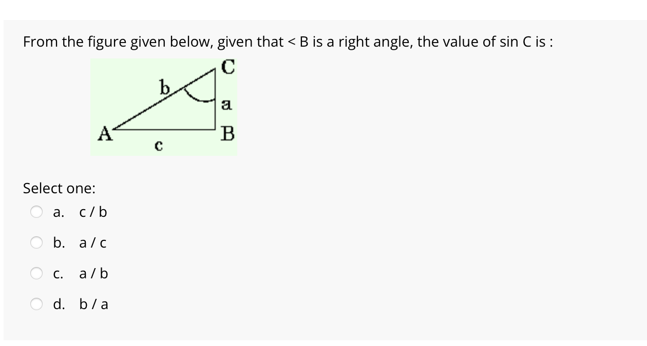
Solved Given The Figure Shown Below Chegg

Solved Given The Figure Shown Below Chegg Our expert help has broken down your problem into an easy to learn solution you can count on. there’s just one step to solve this. f= 2i 4j 10k |f| =1 not the question you’re looking for? post any question and get expert help quickly. Suppose charge 3 is placed in between the other two charges, as shown below. use this diagram to show the force vectors representing all the forces acting on charge 3.

Solved For The Figure Shown Chegg Problem 3: given the circuit in the figure below, with v1 = 12 v, calculate the output voltage (across the open terminals), the current leaving the source, and the current. To solve parts (g) and (h), we need to understand the circuit configuration. the given resistances are r 1 = 1 2. 0 Ω r1 = 12.0Ω, r 2 = 3. 4 5 Ω r2 = 3.45Ω, and the voltage v = 6. 4 5 v v = 6.45v. we need to find the voltage across a 3. 0 0 Ω 3.00Ω resistor and the current through it. Consider the circuit shown in the figure below. [15 points] (a) obtain an expression for the apparent power, s, by the sending end voltage source, your answer should only contain vs, vr, δ, x, and b. [5 points] (b) obtain an expression for the real power generated by the sending end voltage source, vs. Complete the timing diagram given in the figure, which shows the signal values with 1 ns resolution. there will be a slight difference in the delay from d to output dependent upon whether the d has to go through the inverter.

Solved From The Figure Given Below Given That Chegg Consider the circuit shown in the figure below. [15 points] (a) obtain an expression for the apparent power, s, by the sending end voltage source, your answer should only contain vs, vr, δ, x, and b. [5 points] (b) obtain an expression for the real power generated by the sending end voltage source, vs. Complete the timing diagram given in the figure, which shows the signal values with 1 ns resolution. there will be a slight difference in the delay from d to output dependent upon whether the d has to go through the inverter. Given the beam shown below solve the following. calculating support reactions for beams is a fundamental concept in statics and structural analysis. it involves applying equilibrium equations (sum of forces and moments equal to zero) to determine the unknown forces and moments at the supports. 22. what is shown in the figure below? not the question you’re looking for? post any question and get expert help quickly. Calculate the current through 48 Ω resistor in the circuit shown in the figure. assume the diodes to be of silicon and forward resistance of each diode is 1 Ω. The solution includes drawing a mohr's circle diagram and identifying maximum and minimum principal stresses as well as normal and shear stresses on two given planes.

Solved Use The Given Figure Below Chegg Given the beam shown below solve the following. calculating support reactions for beams is a fundamental concept in statics and structural analysis. it involves applying equilibrium equations (sum of forces and moments equal to zero) to determine the unknown forces and moments at the supports. 22. what is shown in the figure below? not the question you’re looking for? post any question and get expert help quickly. Calculate the current through 48 Ω resistor in the circuit shown in the figure. assume the diodes to be of silicon and forward resistance of each diode is 1 Ω. The solution includes drawing a mohr's circle diagram and identifying maximum and minimum principal stresses as well as normal and shear stresses on two given planes.

Figure Chegg Calculate the current through 48 Ω resistor in the circuit shown in the figure. assume the diodes to be of silicon and forward resistance of each diode is 1 Ω. The solution includes drawing a mohr's circle diagram and identifying maximum and minimum principal stresses as well as normal and shear stresses on two given planes.
Comments are closed.