Solved For The Single Link Robot Arm System Given In Figure Chegg

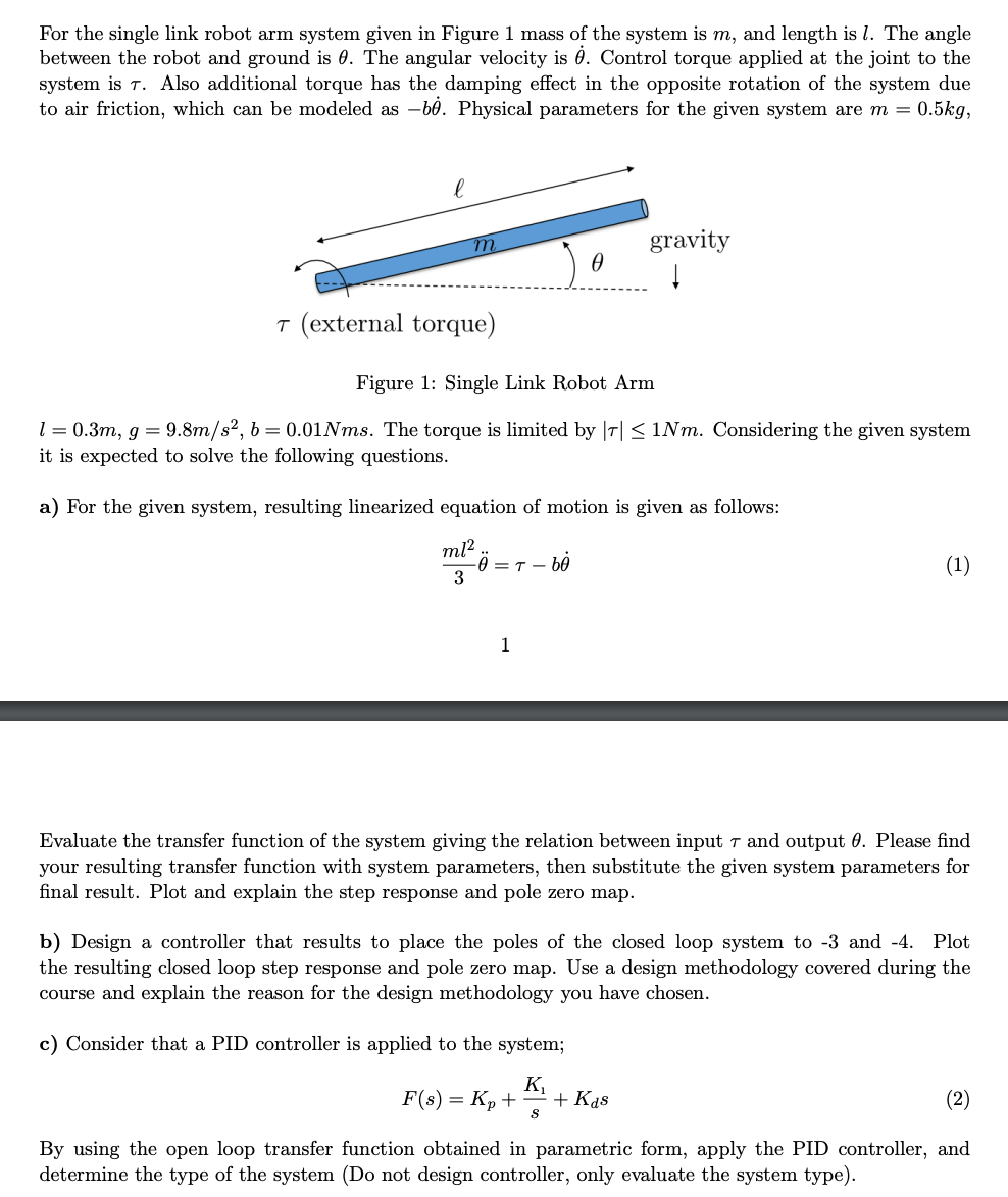
Solved For The Single Link Robot Arm System Given In Figure Chegg Question: for the single link robot arm system given in figure 1 mass of the system is m, and length is l. the anglebetween the robot and ground is θ. the angular velocity is θ˙. control torque applied at the joint to thesystem is τ. A single link of a robot arm is shown in figure p2.24. the arm mass is m and its center of mass is located a distance l from the joint, which is driven by a motor torque t m through two pairs of spur gears.

Solved For The Single Link Robot Arm System Given In Figure Chegg Please find your resulting transfer function with system parameters, then substitute the given system parameters for final result. plot and explain the step response and pole zero map. Solution: suppose that we know that the robot is somewhere to the left of the landmark and that its heading is unknown. suppose that the robot makes a measurement of a single landmark to obtain a distance and bearing relative to the robot (shown as an arrow in the follow figures). A single link of a robot arm is shown in figure. the arm mass is m and its center of mass is located a distance l from the joint, which is driven by a motor torque tm through two pairs of spur gears. we model the arm as a pendulum with a concentrated mass m. thus we take the arm's moment of inertia ig, to be zero. Mit robotics problem set focusing on kinematic equations, inverse kinematics, and workspace analysis for robot arm configurations.

Solved For The Single Link Robot Arm System Given In Figure Chegg A single link of a robot arm is shown in figure. the arm mass is m and its center of mass is located a distance l from the joint, which is driven by a motor torque tm through two pairs of spur gears. we model the arm as a pendulum with a concentrated mass m. thus we take the arm's moment of inertia ig, to be zero. Mit robotics problem set focusing on kinematic equations, inverse kinematics, and workspace analysis for robot arm configurations. Please find your resulting transfer function with system parameters, then substitute the given system parameters for final result. plot and explain the step response and pole zero map. Example 6: consider the single link robot arm shown in figure single link robot. the kinetic energy of the system is given by example 6: the potential energy is given as where m is the total mass of the link and is the distance from the joint axis. Please find your resulting transfer function with system parameters, then substitute the given system parameters for final result. plot and explain the step response and pole zero map. Please find your resulting transfer function with system parameters, then substitute the given system parameters for final result. plot and explain the step response and pole zero map.
Comments are closed.