Solved Experiment Two 1 Designing Mod 10 Counter By 74161 Chegg

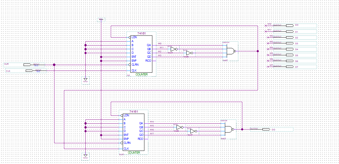
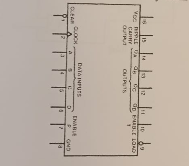
Solved Experiment Two 1 Designing Mod 10 Counter By 74161 Chegg Here’s the best way to solve it. 1. mod 10 counter the given mod 10 counter using 74161 chip was built a …. To design the mod 10 counter using the first 74161 chip, first set the desired preset value for the counter by configuring the data inputs (d 0, d 1, d 2, and d 3) correctly.

Solved 1 The Counter You Constructed In This Experiment Was Chegg Objective: to design a mod 10 counter using jk flip flops. the clock pulse for the counter will be generated using a 555 timer as an astable multivibrator. the output must be displayed on a seven segment display. your solution’s ready to go! our expert help has broken down your problem into an easy to learn solution you can count on. Calculate the total period t based on the given frequency of 10 hz using the formula t = 1 f. To start designing a modulus 12 counter using the 74161, configure the 74161 to reset when the count reaches 1011 (decimal 11). To design a mod 10 counter using jk flip flops. the clock pulse for the counter will be generated using a 555 timer as an astable multivibrator. the output must be displayed on a seven segment display. 2.2. reference: manufacturer's data sheets of the ha17555 or the ne555p ti or the lm555 555 timer ic, the 74ls47 decoder and the 74hct112 jk.

Chegg Pdf To start designing a modulus 12 counter using the 74161, configure the 74161 to reset when the count reaches 1011 (decimal 11). To design a mod 10 counter using jk flip flops. the clock pulse for the counter will be generated using a 555 timer as an astable multivibrator. the output must be displayed on a seven segment display. 2.2. reference: manufacturer's data sheets of the ha17555 or the ne555p ti or the lm555 555 timer ic, the 74ls47 decoder and the 74hct112 jk. To avoid lock out and make sure that at the starting point the counter is in its initial state or it comes to its initial state within few clock cycles, external logic circuitry is to be provided and so we design the counter assuming the next state to be the initial state, from each unused states. Counting sequence of decade counter. a decade counter is called as mod 10 or divide by 10 counter. it counts from 0 to 9 and again reset to 0. it counts in natural binary sequence. here 4 t flip flops are used. it resets after q 3 q 2 q 1 q 0 = 1001. Reset logic: implement reset logic to reset the counter to 0 after reaching 9. this can be achieved using additional logic gates to detect the count of 9 and generate a reset signal. There are 2 steps to solve this one. to design a mod 10 counter using j k flip flops, along with a 555 timer for the clock pulse generati 2.1. objective: to design a mod 10 counter using jk flip flops. the clock pulse for the counter wil be generated using a 555 timer as an astable multivibator.

Chegg Pdf To avoid lock out and make sure that at the starting point the counter is in its initial state or it comes to its initial state within few clock cycles, external logic circuitry is to be provided and so we design the counter assuming the next state to be the initial state, from each unused states. Counting sequence of decade counter. a decade counter is called as mod 10 or divide by 10 counter. it counts from 0 to 9 and again reset to 0. it counts in natural binary sequence. here 4 t flip flops are used. it resets after q 3 q 2 q 1 q 0 = 1001. Reset logic: implement reset logic to reset the counter to 0 after reaching 9. this can be achieved using additional logic gates to detect the count of 9 and generate a reset signal. There are 2 steps to solve this one. to design a mod 10 counter using j k flip flops, along with a 555 timer for the clock pulse generati 2.1. objective: to design a mod 10 counter using jk flip flops. the clock pulse for the counter wil be generated using a 555 timer as an astable multivibator.

Four Counter Designs Will Be Made With The 74161 Chegg Reset logic: implement reset logic to reset the counter to 0 after reaching 9. this can be achieved using additional logic gates to detect the count of 9 and generate a reset signal. There are 2 steps to solve this one. to design a mod 10 counter using j k flip flops, along with a 555 timer for the clock pulse generati 2.1. objective: to design a mod 10 counter using jk flip flops. the clock pulse for the counter wil be generated using a 555 timer as an astable multivibator.
Comments are closed.