Solved Exercise 2 10 Consider The Potentiometer Circuit Chegg

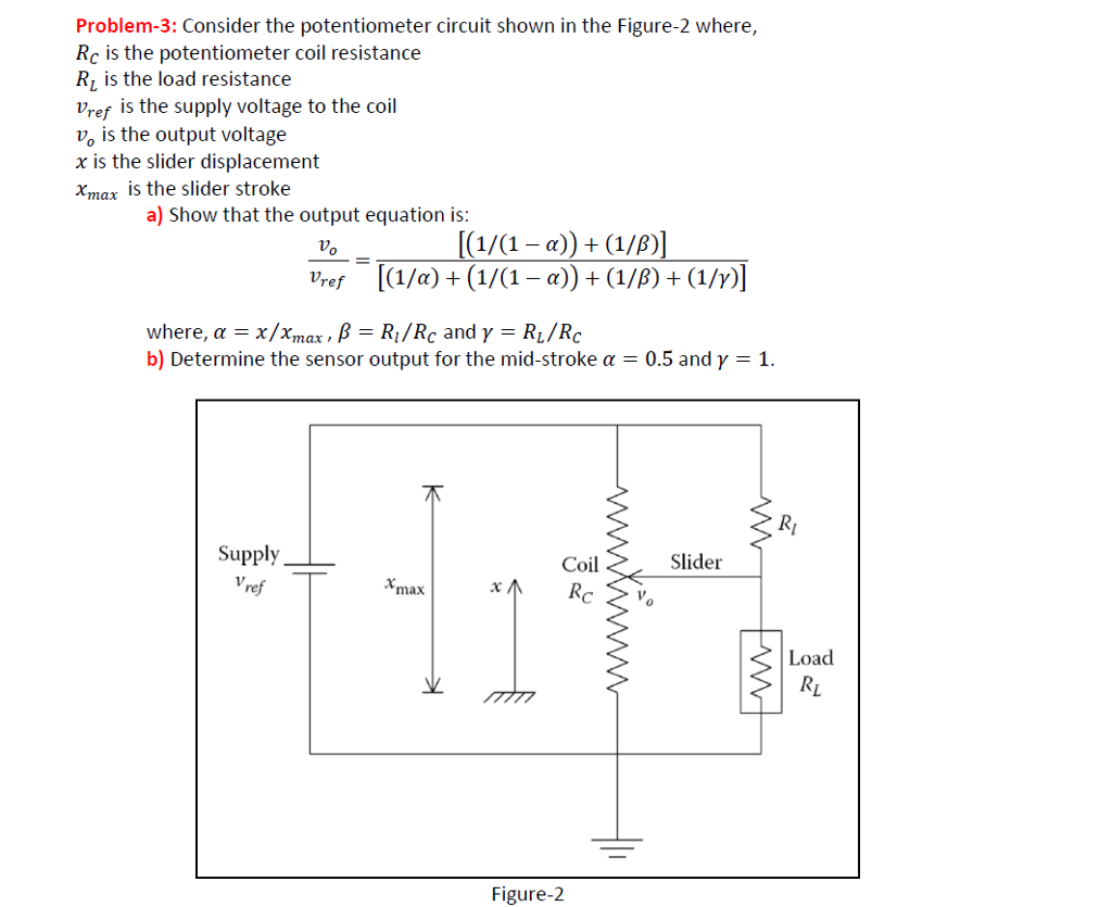
Solved Consider The Potentiometer Circuit Shown In The Chegg Question: exercise 2.10 consider the potentiometer circuit shown in figure 9. show that the output equation is 2 3 vo = vref 1 =, rc rl = b and rl i mar rc c 1=a (1 b) (1 7) where = 7. determine the sensor output for the midstroke = a = 0.5) when r = y = 1. show that r1 = rc gives zero error. Let us redraw the circuit with the potentiometer divided by the sliding contact into two parts with resistances rx and ry (see illustrating picture). we can find the resistances of each part directly.

Solved Exercise 2 10 Consider The Potentiometer Circuit Chegg Consider the potentiometer circuit for determining the internal resistance of a cell. when switch s is open, the balance point is found to be at 75cm os the wire. Consider the potentiometer circuit arranged as shown in the figure. the potentiometer wire is 600 cm long. if the distance from point a, where the jockey touches the wire to get zero deflection in the galvanometer, is (x 0.2) meters, then what is the value of x?. Identify all the resistors in the circuit and compute for the equivalent resistance. A two track incremental encoder installed on a rotating shaft has 1000 slots evenly distributed along the circumference and has the output sampled at 10 mhz.

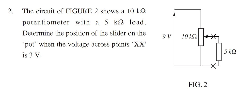
Solved 2 The Circuit Of Figure 2 Shows A 10 Kω Chegg Identify all the resistors in the circuit and compute for the equivalent resistance. A two track incremental encoder installed on a rotating shaft has 1000 slots evenly distributed along the circumference and has the output sampled at 10 mhz. By connecting a potentiometer as shown below we can create a device that converts α into a voltage vo. all voltages are measured relative to ground. your answers below will involve variables such as v 1, v 2, r and r p, you should enter a valid infix expression as you would in python, e.g. 3*v 1 r p 2. the asterisks are optional. Potentiometer is used for the accurate measurement of potential differences, current and resistances. For the potentiometer arrangement shown in the figure, length of wire ab is 100 cm and its resistance is 9Ω. find the length ac for which the galvanometer g will show zero deflection. Here’s the best way to solve it. start by identifying and defining the resistances in the potentiometer circuit: r e for the equal end resistors, r c for the resistance of the potentiometer coil, r l for the load resistor, and r x as the resistance of the coil segment in parallel with the load.

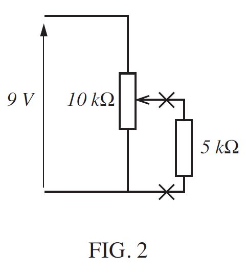
Solved The Circuit Of Figure 2 Shows A 10 K Chegg By connecting a potentiometer as shown below we can create a device that converts α into a voltage vo. all voltages are measured relative to ground. your answers below will involve variables such as v 1, v 2, r and r p, you should enter a valid infix expression as you would in python, e.g. 3*v 1 r p 2. the asterisks are optional. Potentiometer is used for the accurate measurement of potential differences, current and resistances. For the potentiometer arrangement shown in the figure, length of wire ab is 100 cm and its resistance is 9Ω. find the length ac for which the galvanometer g will show zero deflection. Here’s the best way to solve it. start by identifying and defining the resistances in the potentiometer circuit: r e for the equal end resistors, r c for the resistance of the potentiometer coil, r l for the load resistor, and r x as the resistance of the coil segment in parallel with the load.
Comments are closed.