Solved Design A Causal Linear Phase Low Pass Fir Filter Chegg

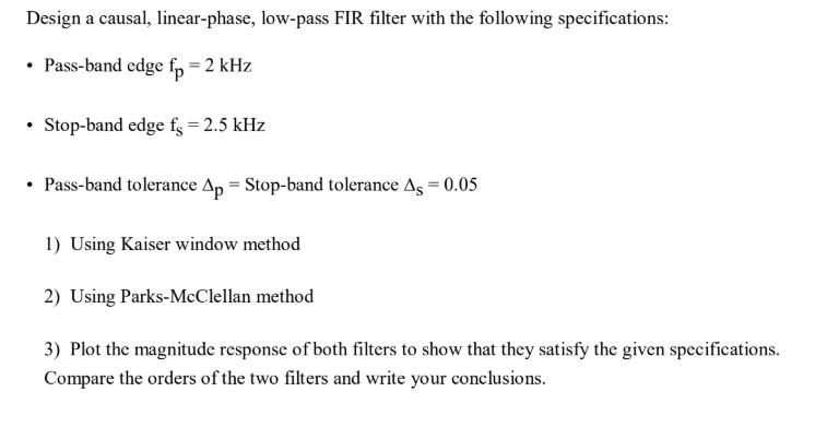
Solved Design A Causal Linear Phase Low Pass Fir Filer Chegg Design a causal, linear phase, low pass fir filter with the following specifications: • pass band edge fp = 2 khz • stop band edge fs = 2.5 khz • pass band tolerance ap = stop band tolerance as = 0.05 • sampling frequency = 20 khz 1) using kaiser window method 2) using parks mcclellan method 3) plot the magnitude response of both. This example shows how to design lowpass fir filters. you can extend many of the concepts presented here to other responses such as highpass, bandpass, and others.

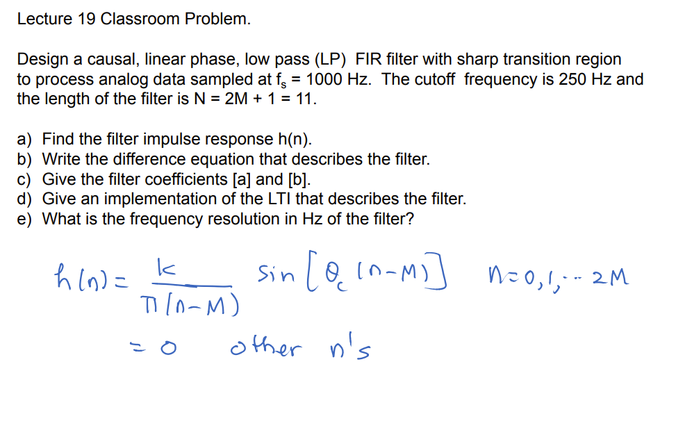
Lecture 19 Classroom Problem Design A Causal Linear Chegg Design a normalized linear phase fir low pass lter having phase delay of = 4 and at least 40 db attenuation in the stopband. also obtain the magnitude frequency response of the lter. (solved): design causal linear phase low pass fir filter following specifications pass band edge fp q37132344…. In this article, we will discuss several design examples of fir filters using the window method. the simulated frequency response of the designed filters will be compared with the target specifications. Suppose we want to design a digital filter for a signal having bandwidth of 8 khz, and we have to use a 5 pole butterworth filter (commercially available for low cost) for both antialiasing and reconstruction filters.

Solved Low Pass Fir Filter Design By Windows The Design Of Chegg In this article, we will discuss several design examples of fir filters using the window method. the simulated frequency response of the designed filters will be compared with the target specifications. Suppose we want to design a digital filter for a signal having bandwidth of 8 khz, and we have to use a 5 pole butterworth filter (commercially available for low cost) for both antialiasing and reconstruction filters. Why linear phase: example (2) consider the same system given on the previous slide, but let us change the frequency of the cosine signal. when !2 = 0:47 , then the delay is (!2)=!2 = 0:14. Obtain a causal and linear phase fir filter with time delay of 3 samples; iii. sketch the magnitude and phase responses of the fir filter. (b) the system function of. your solution’s ready to go! our expert help has broken down your problem into an easy to learn solution you can count on. We address the problem of designing an fir filter that meets specifications of limited devia tion from the ideal response in specified frequency bands. Let the input to this filter be a sum of 3 cosine sequences of angular frequencies: 0.2 rad samples, 0.5 rad samples, and 0.8 rad samples, respectively. determine the impulse response coefficients so that the filter passes only the midfrequency component of the input.

Solved Low Pass Fir Filter Design By Windows The Design Of Chegg Why linear phase: example (2) consider the same system given on the previous slide, but let us change the frequency of the cosine signal. when !2 = 0:47 , then the delay is (!2)=!2 = 0:14. Obtain a causal and linear phase fir filter with time delay of 3 samples; iii. sketch the magnitude and phase responses of the fir filter. (b) the system function of. your solution’s ready to go! our expert help has broken down your problem into an easy to learn solution you can count on. We address the problem of designing an fir filter that meets specifications of limited devia tion from the ideal response in specified frequency bands. Let the input to this filter be a sum of 3 cosine sequences of angular frequencies: 0.2 rad samples, 0.5 rad samples, and 0.8 rad samples, respectively. determine the impulse response coefficients so that the filter passes only the midfrequency component of the input.

Solved Design A Linear Phase Fir Low Pass Filter Of Length Chegg We address the problem of designing an fir filter that meets specifications of limited devia tion from the ideal response in specified frequency bands. Let the input to this filter be a sum of 3 cosine sequences of angular frequencies: 0.2 rad samples, 0.5 rad samples, and 0.8 rad samples, respectively. determine the impulse response coefficients so that the filter passes only the midfrequency component of the input.
Comments are closed.