Solved 2 Question Consider The Following System In Figure Chegg

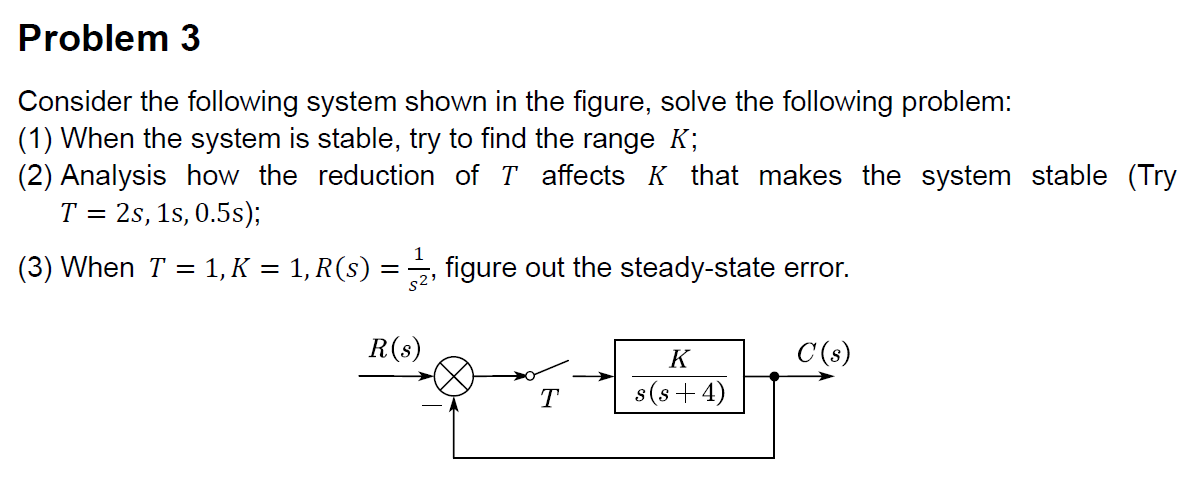
Solved 2 Question Consider The Following System In Figure Chegg Question: consider the following system in figure 2. (a) find the system function relating the z transforms of the input and output. (b) write the difference equation that satisfies the input x [n) and output y [n]. * [n] y [n] fig. 2: example system. your solution’s ready to go!. Q2 consider the system shown in figure q2, show that it can be solved by using block reduction method and mason's gain formula. (a) use block diagram reduction techniques to obtain the transfer function of the system. (b) convert the block diagram in figure q2 to signal flow graph. (c) use mason's rule to obtain the transfer function of the system.

Solved Consider The Following System Shown In Figure 2 And Chegg Note: the following set of symbols and units is used throughout this book: wf) = v (volts), i (f) = a (amp g (t) = q (coulombs), c = f (farads), r = © (ohms), g = u (mhos), lz = h (henries). To plot the response curves, we need to solve the state equations for the given input force u = 10 n. we can use numerical methods such as euler's method or a numerical solver to solve the equations. Problem 5 .1 7pp for the system shown in fig., determine the characteristic equation and sketch the root locus of it with respect to positive values of the parameter c. give l (s), a (s), and b (s), and be sure to show with arrows the direction in which c increases on the locus. Problem #2 [10 points] consider the following system shown in figure 2 and assume that all the system initial conditions are zero. determine the laplace transform of the system output for the following system inputs: i (t) e and r2 (t) ut), where u (t) is the unit step function.

Solved Consider The Following System Shown In Figure 2 And Chegg Problem 5 .1 7pp for the system shown in fig., determine the characteristic equation and sketch the root locus of it with respect to positive values of the parameter c. give l (s), a (s), and b (s), and be sure to show with arrows the direction in which c increases on the locus. Problem #2 [10 points] consider the following system shown in figure 2 and assume that all the system initial conditions are zero. determine the laplace transform of the system output for the following system inputs: i (t) e and r2 (t) ut), where u (t) is the unit step function. There are 2 steps to solve this one. problem 2. consider the system shown in fig. 2. for each case given, find the steady state error for (i) a unit step input; (ii) a unit ramp input. assume in each case that the closed loop system is stable. (@) g,o) ) g,o) (a )o 4) g, (g) 7 (s 2) s (s 1 6) (s2)s 4) s2 3s s (s2 2) g (s) figure 2. Question: consider the following system shown in figure . this system is whatwe refer to as "observer based feedback controller". Solved question 7solve the following system using x 8 y 5 z 2 graph functions, plot points, visualize algebraic equations, add sliders, animate graphs,. a value c is said to be a root of a polynomial p x if p c =0. A) consider the system shown in figure 3. simplify this diagram. b) convert the following block diagram shown in figure 4 into its equivalent signal flow graph. there are 2 steps to solve this one.

Solved Consider The Following System Shown In Figure 2 And Chegg There are 2 steps to solve this one. problem 2. consider the system shown in fig. 2. for each case given, find the steady state error for (i) a unit step input; (ii) a unit ramp input. assume in each case that the closed loop system is stable. (@) g,o) ) g,o) (a )o 4) g, (g) 7 (s 2) s (s 1 6) (s2)s 4) s2 3s s (s2 2) g (s) figure 2. Question: consider the following system shown in figure . this system is whatwe refer to as "observer based feedback controller". Solved question 7solve the following system using x 8 y 5 z 2 graph functions, plot points, visualize algebraic equations, add sliders, animate graphs,. a value c is said to be a root of a polynomial p x if p c =0. A) consider the system shown in figure 3. simplify this diagram. b) convert the following block diagram shown in figure 4 into its equivalent signal flow graph. there are 2 steps to solve this one.

Solved Consider The Following System Shown In The Figure Chegg Solved question 7solve the following system using x 8 y 5 z 2 graph functions, plot points, visualize algebraic equations, add sliders, animate graphs,. a value c is said to be a root of a polynomial p x if p c =0. A) consider the system shown in figure 3. simplify this diagram. b) convert the following block diagram shown in figure 4 into its equivalent signal flow graph. there are 2 steps to solve this one.

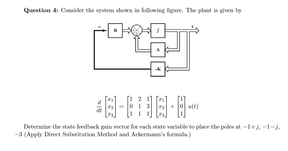
Solved Question 4 Consider The System Shown In Following Chegg
Comments are closed.