Solved 2 An Analog Filter With The Transfer Function N S 0 55 5

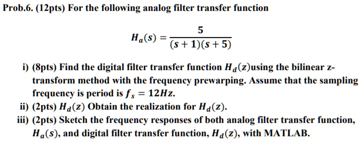
Solved For The Following Analog Filter Transfer Function Ha S 5 Your solution’s ready to go! our expert help has broken down your problem into an easy to learn solution you can count on. see answer. One can prevent the aliasing by making the primary strip wide enough (small enough t) to include all the analog filter poles. thus each horizontal strip of the s plane of width 2p t is mapped onto the entire z plane.

Solved 5 Consider An Analog Filter Transfer Function Given Chegg A digital filter has the impulse response h [n] = [0.5 0.5] and is implemented at a sampling frequency of fs = 44.1khz. an input signal x [n] = 10 10 cos (0.5tn θ) 10 cos (ωn φ) is sent through the filter, giving the output y [n]. The transfer function of a filter is the ratio of the output to input time functions. it can be shown that the impulse response of a filter defines its bandwidth. Problem 5: design butterworth filter using bilinear transformation solution ws = 0 pi rad: wp =0 pi rad. then assume t= 1 sec prewrapping the frequency for n=2 the transfer function is cut off frequency. From normalized transfer function lpf, hpf, bpf bsf can be obtained by suitable transformation to the normalized lpf speci cation. | determine the poles of lowpass butterworth lter for n=3. sketch the location of poles on s plane and hence determine the normalized transfer function of lowpass lter.

Solved The Transfer Function Of An Analog Filter System Is Chegg Problem 5: design butterworth filter using bilinear transformation solution ws = 0 pi rad: wp =0 pi rad. then assume t= 1 sec prewrapping the frequency for n=2 the transfer function is cut off frequency. From normalized transfer function lpf, hpf, bpf bsf can be obtained by suitable transformation to the normalized lpf speci cation. | determine the poles of lowpass butterworth lter for n=3. sketch the location of poles on s plane and hence determine the normalized transfer function of lowpass lter. Analog filters, whether active or passive, always follow a standard transfer function, normally in the complex s domain alias laplace notation. i was not able to find a comprehensive list of all the general transfer functions, so i decided to create one myself. As it is well known butterworth and chebyshev filters have explicit ways of calculating the order, derived by its polynomials. for instance, for butterworth filters:. The document describes the steps to design an analog low pass butterworth filter based on given specifications for the pass band and stop band frequencies and tolerances. Step 1 8step 1: first, let's find the transfer function of the analog filter. the transfer function is given as n (s) = 0.55 (5² √25 1).step 2 8step 2: next, we need to convert the analog transfer function to its digital form using the invariant impulse response method.

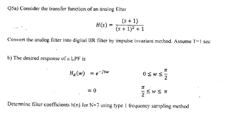
Solved Q5a Consider The Transfer Function Of An Analog Chegg Analog filters, whether active or passive, always follow a standard transfer function, normally in the complex s domain alias laplace notation. i was not able to find a comprehensive list of all the general transfer functions, so i decided to create one myself. As it is well known butterworth and chebyshev filters have explicit ways of calculating the order, derived by its polynomials. for instance, for butterworth filters:. The document describes the steps to design an analog low pass butterworth filter based on given specifications for the pass band and stop band frequencies and tolerances. Step 1 8step 1: first, let's find the transfer function of the analog filter. the transfer function is given as n (s) = 0.55 (5² √25 1).step 2 8step 2: next, we need to convert the analog transfer function to its digital form using the invariant impulse response method.

Solved 6 The Transfer Function Of An Analog Filter Is H S Chegg The document describes the steps to design an analog low pass butterworth filter based on given specifications for the pass band and stop band frequencies and tolerances. Step 1 8step 1: first, let's find the transfer function of the analog filter. the transfer function is given as n (s) = 0.55 (5² √25 1).step 2 8step 2: next, we need to convert the analog transfer function to its digital form using the invariant impulse response method.
Comments are closed.