Solved 1 Given The System Shown Find The Following A The Chegg

Solved 1 Given The System Shown Find The Following A The Chegg Here’s the best way to solve it. 1. given the system shown in figure 1, find the following: a. the closed loop transfer function b. the system type c. the steady state error for an input 5u (t). d. the steady state error for an input 5tu (t). r (s) c (s) 2 10 s (s 1) (s 3) (s 4) 2s figure 1. not the question you’re looking for?. For the rotational mechanical system with gears shown in figure p2.18, find the transfer function, g(s) = 0^(s) t(s). the gears have inertia and bear ing friction as shown.

Solved 1 Given The System Shown Find The Following A The Chegg Problem 5 .1 7pp for the system shown in fig., determine the characteristic equation and sketch the root locus of it with respect to positive values of the parameter c. give l (s), a (s), and b (s), and be sure to show with arrows the direction in which c increases on the locus. The closed loop transfer function can be found by multiplying the transfer function of the plant (r (s)) with the transfer function of the controller (c (s)). in this case, the transfer function of the plant is given as 10 (s (s 1) (s 3) (s 4)) and the transfer show more…. This document presents a series of solved problems related to control systems, focusing on the reduction of block diagrams, determination of transfer functions, and analysis of root locus techniques. Our expert help has broken down your problem into an easy to learn solution you can count on. there are 2 steps to solve this one.

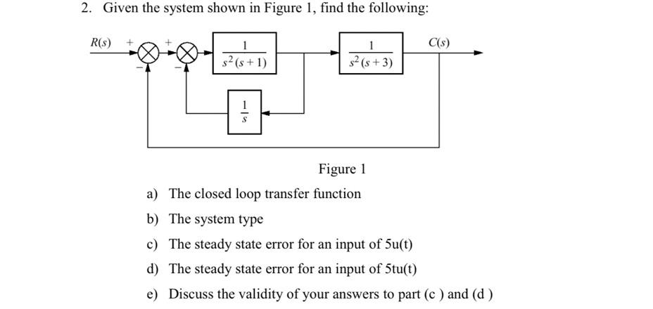
Solved 2 Given The System Shown In Figure 1 Find The Chegg This document presents a series of solved problems related to control systems, focusing on the reduction of block diagrams, determination of transfer functions, and analysis of root locus techniques. Our expert help has broken down your problem into an easy to learn solution you can count on. there are 2 steps to solve this one. In figure 3 59 (a) we assume that displacements x,, x, and y are measured from their respective steady state positions.then the equations of motion for the mechanical system shown in figure 3 59 (a) are chapter 3 mathematical modeling of dynamic systems f bl (x, x,) k, (x, x,) = b, (x, y) b4f" y) = k2y by taking the laplace. Show that the closed loop system of the first system is of a second order. find the range of gains for closed loop stability, the critical gain and the frequency of resulting marginally stable oscillations. Given the system shown in figure 1, find the following: figure 1 a) the closed loop transfer function b) the system type c) the steady state error for an input of 5u (t) d) the steady state error for an input of 5 tu (t) e) discuss the validity of your answers to part (c) and (d). Problem 7 find the unity feedback system that is equivalent to the system shown in figure p5.7.

Solved Given The System Shown Find The Following The Chegg In figure 3 59 (a) we assume that displacements x,, x, and y are measured from their respective steady state positions.then the equations of motion for the mechanical system shown in figure 3 59 (a) are chapter 3 mathematical modeling of dynamic systems f bl (x, x,) k, (x, x,) = b, (x, y) b4f" y) = k2y by taking the laplace. Show that the closed loop system of the first system is of a second order. find the range of gains for closed loop stability, the critical gain and the frequency of resulting marginally stable oscillations. Given the system shown in figure 1, find the following: figure 1 a) the closed loop transfer function b) the system type c) the steady state error for an input of 5u (t) d) the steady state error for an input of 5 tu (t) e) discuss the validity of your answers to part (c) and (d). Problem 7 find the unity feedback system that is equivalent to the system shown in figure p5.7.
Comments are closed.