Solution Half Adder Full Adder Logic Circuit K Map Parity Bit

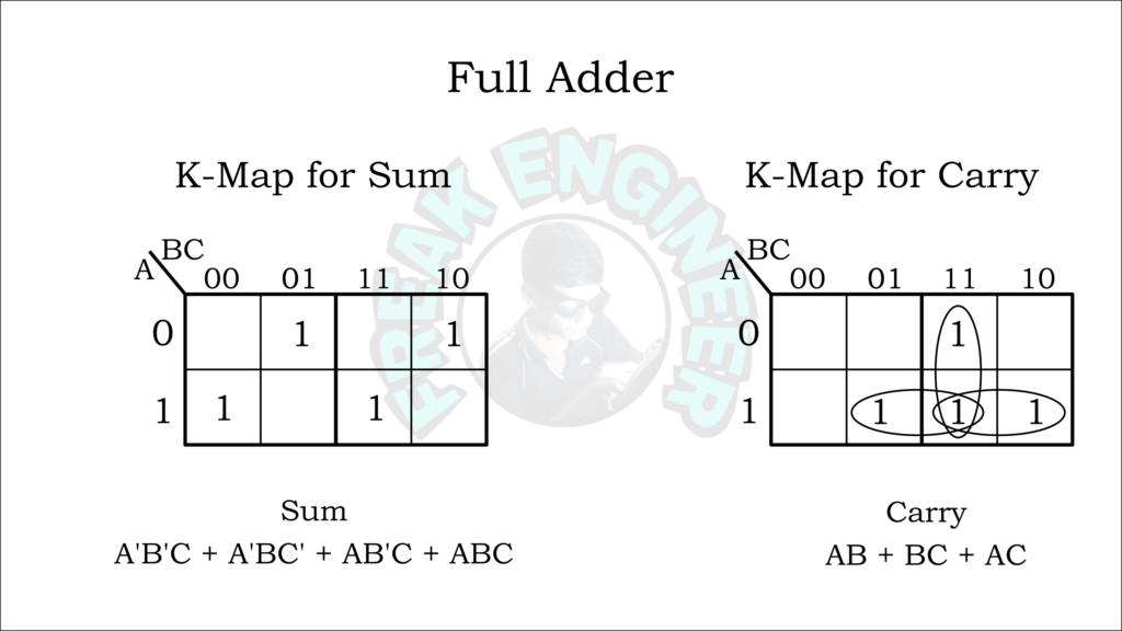
Solution Half Adder Full Adder Logic Circuit K Map Parity Bit Half and full adder are used in combinational circuit design of microprocessor and we explained the truth table, circuit, and k map for both. To overcome the above limitation faced with half adders, full adders are implemented. it is a arithmetic combinational logic circuit that performs addition of three single bits.

Rancangan Rangkaian Logika Dengan K Map Dan Full Adder Half Adder In this tutorial, we will learn about the half and full adders, designing of a full adder using half adder in digital electronics. Draw the logic diagram and verify the correctness of the design. • add two binary numbers and produce two binary outputs. • arithmetic sum of three bits. each full adder has two levels, and total 4 × 2 = 8 levels. the time required will be more, because the carry has to propagate from the least significant bit to the most significant bit. Finally , one can try a k map solution. the rst step is to write out the truth table in the form b elo w, with the input states the headings of ro ws and columns of a table, and the corresp onding outputs within, as sho wn b elo w. With the help of the truth table, we can design a karnaugh map or k map for half adder to obtain a boolean expression. this boolean expression helps us to design a half adder with an xor gate and and gate. the operation of half adder is limited because it can only add two bit binary digits.

Half Adder Full Adder Truth Table Logic Circuit Graphicmaths Finally , one can try a k map solution. the rst step is to write out the truth table in the form b elo w, with the input states the headings of ro ws and columns of a table, and the corresp onding outputs within, as sho wn b elo w. With the help of the truth table, we can design a karnaugh map or k map for half adder to obtain a boolean expression. this boolean expression helps us to design a half adder with an xor gate and and gate. the operation of half adder is limited because it can only add two bit binary digits. With the truth table, the full adder logic can be implemented. you can see that the output s is an xor between the input a and the half adder, sum output with b and c in inputs. The whole idea of writing the boolean expressions in this modified form was to demonstrate the use of a half adder circuit in building a full adder. figure 3.7 (a) shows logic implementation of equations above. In this tutorial, we are going to look at the binary adder and subtractor circuits. we will learn about the half adder, full adder, parallel adder (using multiple full adders), half subtractor, full subtractor and a parallel adder subtractor combination circuit. Explore half and full adder circuit diagram, truth table, working, vhdl code, k map and its implementation using 7483 ic.

Solution Half Adder Full Adder Combinational Logic Circuit Studypool With the truth table, the full adder logic can be implemented. you can see that the output s is an xor between the input a and the half adder, sum output with b and c in inputs. The whole idea of writing the boolean expressions in this modified form was to demonstrate the use of a half adder circuit in building a full adder. figure 3.7 (a) shows logic implementation of equations above. In this tutorial, we are going to look at the binary adder and subtractor circuits. we will learn about the half adder, full adder, parallel adder (using multiple full adders), half subtractor, full subtractor and a parallel adder subtractor combination circuit. Explore half and full adder circuit diagram, truth table, working, vhdl code, k map and its implementation using 7483 ic.

Half Adder And Full Adder Logic Circuit With Truth Table And Symbol In this tutorial, we are going to look at the binary adder and subtractor circuits. we will learn about the half adder, full adder, parallel adder (using multiple full adders), half subtractor, full subtractor and a parallel adder subtractor combination circuit. Explore half and full adder circuit diagram, truth table, working, vhdl code, k map and its implementation using 7483 ic.
Comments are closed.