Quick Review Of The 68hc11 Output Timer Counter Lecture

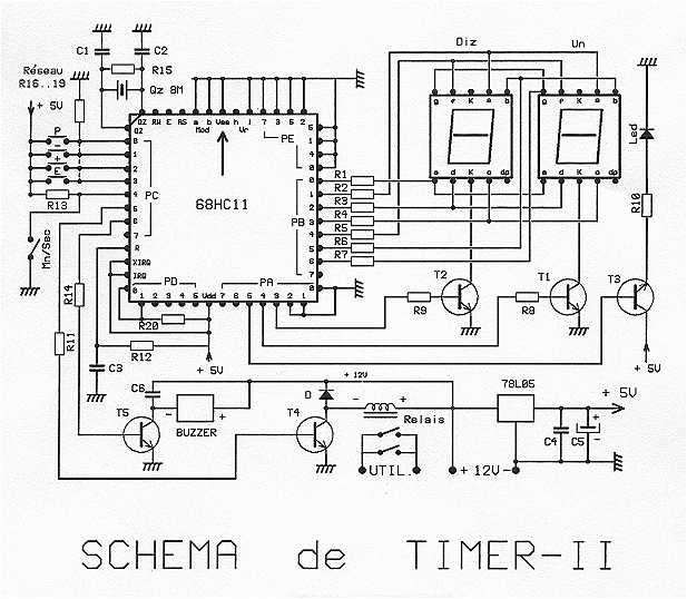
68hc11 As A Digital Timer Under Timer Circuits 7383 Next Gr Quick review of the 68hc11 output timer counter lecture professor allemang 216 subscribers 4. Another important 68hc11 timer function is output compare, which compares the value of the main timer with that of an output compare register once every e clock cycle.

Ppt Ele22mic Lecture 17 Powerpoint Presentation Free Download Id When 68hc11 timer counter tcnt repeatedly overflows after (216 ×p) 2 s, the event(s) or action(s) or instructions on each isr run can be repeated after every 216 × p × 0.5 s, provided p programmed within 64 clock cycles of start up of 68hc11 mcu. Learn about 68hc11 microcontroller timer functions: output compare, real time interrupt, input capture. college level electrical engineering resource. Real time interrupt – produce a period signal for the 68hc11. period the real time interrupt will allow a piece of code to be executed at a given period. this can be used to implement a real time clock. It describes the free running counter, prescalar, timer overflow, input capture registers, and provides examples of using these features to measure time periods, time delays, and the period of a square wave connected to an input pin.

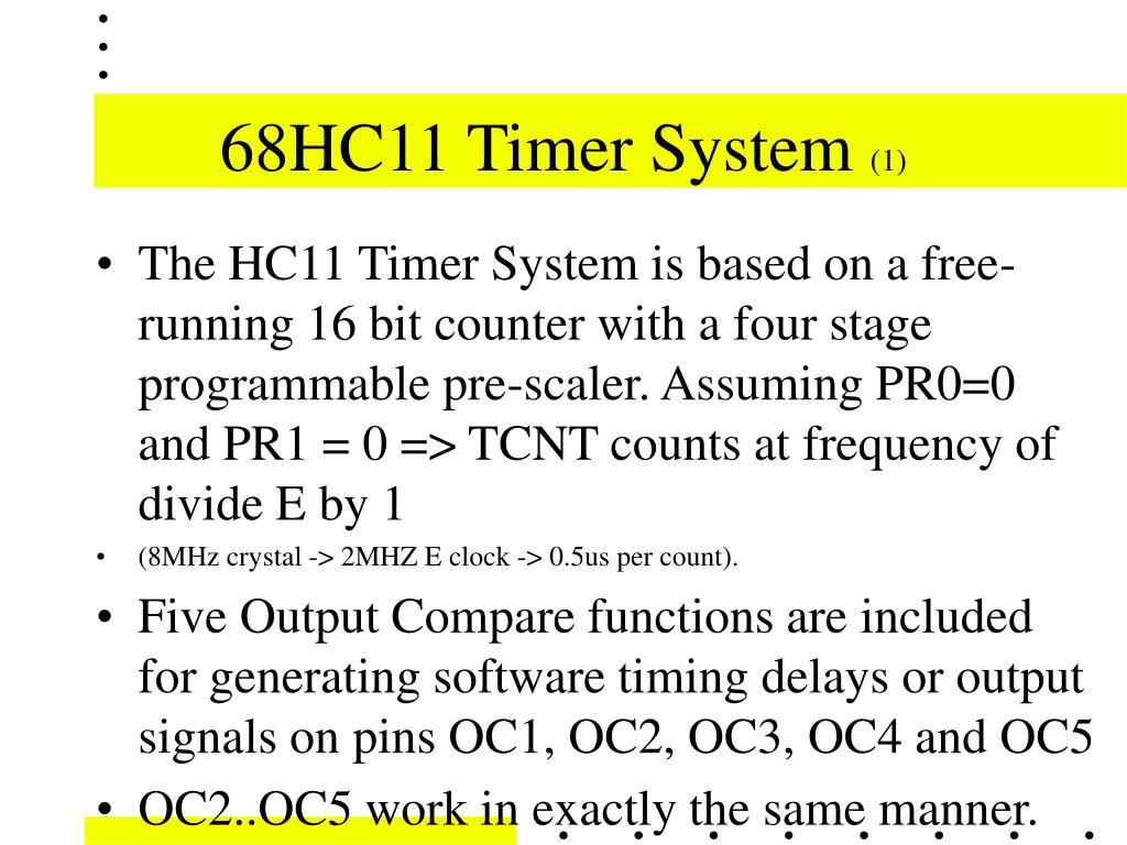
Ppt Ele22mic Lecture 17 Powerpoint Presentation Free Download Id Real time interrupt – produce a period signal for the 68hc11. period the real time interrupt will allow a piece of code to be executed at a given period. this can be used to implement a real time clock. It describes the free running counter, prescalar, timer overflow, input capture registers, and provides examples of using these features to measure time periods, time delays, and the period of a square wave connected to an input pin. The 68hc11 includes a powerful timer subsystem which is capable of simultaneous input captures, output compares, real time interrupts, pulse accumulation and much more. Output compare: set flag (optional interrupt) when timer reaches a certain value can also automatically set clear toggle output bits. Five output compare functions are included for generating software timing delays or output signals on pins oc1, oc2, oc3, oc4 and oc5 oc2 oc5 work in exactly the same manner. the five output compare pins can be used independently to create precise timing for time delays or external logic pulses. The simplest way of generating a precise pwm waveform with arbitrary duty cycle and period is to use a single output compare to automatically turn on and off an output pin and an interrupt service routine that reprograms the output compare after each transition.

Ppt Ele22mic Lecture 17 Powerpoint Presentation Free Download Id The 68hc11 includes a powerful timer subsystem which is capable of simultaneous input captures, output compares, real time interrupts, pulse accumulation and much more. Output compare: set flag (optional interrupt) when timer reaches a certain value can also automatically set clear toggle output bits. Five output compare functions are included for generating software timing delays or output signals on pins oc1, oc2, oc3, oc4 and oc5 oc2 oc5 work in exactly the same manner. the five output compare pins can be used independently to create precise timing for time delays or external logic pulses. The simplest way of generating a precise pwm waveform with arbitrary duty cycle and period is to use a single output compare to automatically turn on and off an output pin and an interrupt service routine that reprograms the output compare after each transition.

Lecture 3 68hc11 Memory Five output compare functions are included for generating software timing delays or output signals on pins oc1, oc2, oc3, oc4 and oc5 oc2 oc5 work in exactly the same manner. the five output compare pins can be used independently to create precise timing for time delays or external logic pulses. The simplest way of generating a precise pwm waveform with arbitrary duty cycle and period is to use a single output compare to automatically turn on and off an output pin and an interrupt service routine that reprograms the output compare after each transition.
Comments are closed.