Problem With Creating Sheet Metal Feature In Solidworks Grabcad Questions

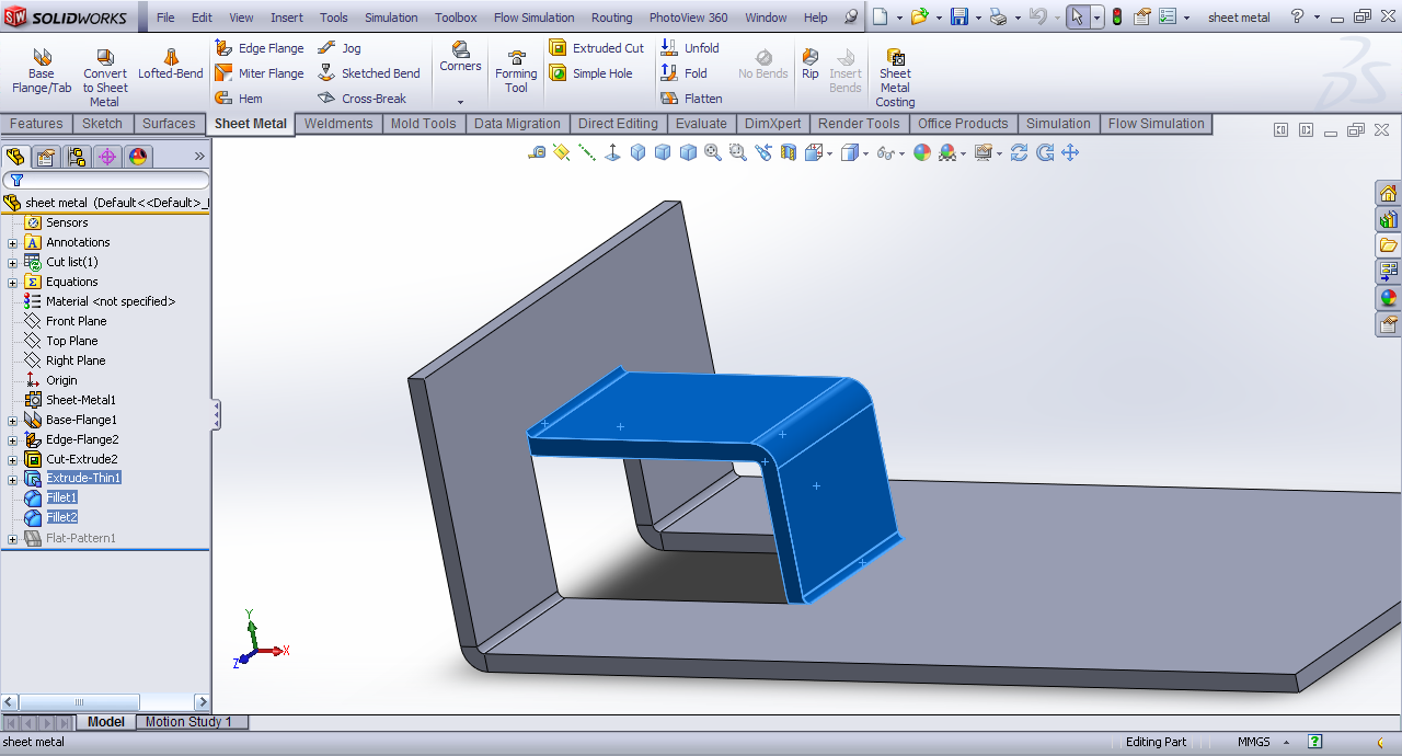
Problem With Creating Sheet Metal Feature In Solidworks Grabcad Questions Can i create the similar flange using sheet metal feature in solidworks. i tried but couldn't merge the edges. you can see the highlighted faces. I attached the image. if you can solve this it will great help. solidworks always showing . 5 mm radius even if thickness is changed. help. thanks.

Problem With Creating Sheet Metal Feature In Solidworks Grabcad Questions Designing sheet metal parts in solidworks can be a challenging yet rewarding task, especially if you aim to create precise, manufacturable designs. however, even seasoned designers can fall prey to common pitfalls that lead to costly errors and production delays. At times, it may appear quicker to use non sheet metal features (boss extrude, etc.), and then insert bends or convert to sheet metal. however, these options are problematic and the least flexible. Curious about how you design a certain 3d printable model or which cad software works best for a particular project? grabcad was built on the idea that engineers get better by interacting with other engineers the world over. ask our community!. It's pretty easy in solidworks using sheet metal features. open a new part. select insert >sheet metal >base flange. this will begin a sheet metal part. note: insert >sheet metal is where you can find all of the sheet metal features. draw the base of your part and dimension accordingly.

Problem With Creating Sheet Metal Feature In Solidworks Grabcad Questions Curious about how you design a certain 3d printable model or which cad software works best for a particular project? grabcad was built on the idea that engineers get better by interacting with other engineers the world over. ask our community!. It's pretty easy in solidworks using sheet metal features. open a new part. select insert >sheet metal >base flange. this will begin a sheet metal part. note: insert >sheet metal is where you can find all of the sheet metal features. draw the base of your part and dimension accordingly. When you click insert bends on the sheet metal toolbar, or click insert > sheet metal > bends, two distinct stages are applied to the sheet metal part. the part is flattened and a bend allowance is added. the developed length is calculated, based on the bend radius and bend allowance. The computer aided design ("cad") files and all associated content posted to this website are created, uploaded, managed and owned by third party users. each cad and any associated text, image or data is in no way sponsored by or affiliated with any company, organization or real world item, product, or good it may purport to portray. Learn sheet metal commands and designing procedure in solid works. Problem with creating sheet metal feature in solidworks | grabcad groups discussions discussions members.
Comments are closed.