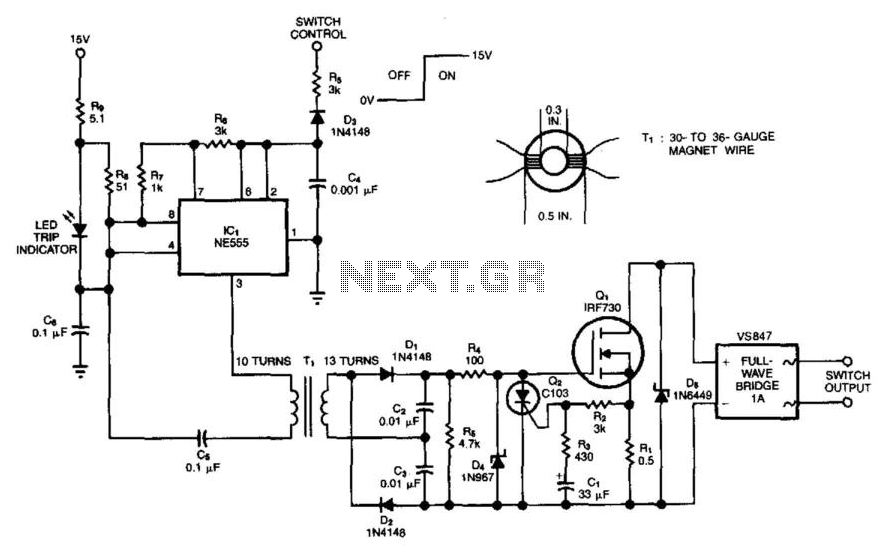
Mosfet As A Switch Using Power Mosfet Switching Power Switch

Using The Power Mosfet As A Switch Pdf Mosfet Field Effect Transistor I want to make a mosfet model having the following parameters in ltspice: $$\mu nc {ox} = 100 \mu a v^2 ; v {th} = 0.5 v, \lambda = 0$$ and to define w and l, where i can change it from one design to another. The threshold voltage of a mosfet decreases as temperature increases. i don't understand this. consider an n type mosfet that is fabricated in a p doped silicon substrate. for a channel inversion l.

Mosfet As A Switch Using Power Mosfet Switching Power Switch Optional: edit the drawing of the auto generated symbol (e.g. for a mosfet, remove the yellow box and draw a mosfet symbol); it is sometimes useful to hide the pin labels by right clicking the pin and selecting none(not visible). save the symbol file. it is located in documents\ltspicexvii\lib\sym\autogenerated; you can leave it there. I am trying to understand this formula to find the transconductance of a mosfet transistor, but i am not getting the passage from the second to the third line. what happened there? thank you. Questions: 1) how to calculate the mosfet input resistor? 2) what are the factors affecting the mosfet input resistor calculation? 3) what will be the maximum, minimum resistor value possible and effect in the circuit if the resistor value is changed (increased or decreased) ? please let me know if any further info is required. And one more question, what exactly does "shorting the gate to source" do to the mosfet, does it mean that by shorting the gate to source, whenever the secondary side of the transformer outputs a current, vgs=0, and thus the switch wont activate, and all current flows through the body diode, is that right?.

Electronics Tutorial About The Power Mosfet As A Switch And Using The Questions: 1) how to calculate the mosfet input resistor? 2) what are the factors affecting the mosfet input resistor calculation? 3) what will be the maximum, minimum resistor value possible and effect in the circuit if the resistor value is changed (increased or decreased) ? please let me know if any further info is required. And one more question, what exactly does "shorting the gate to source" do to the mosfet, does it mean that by shorting the gate to source, whenever the secondary side of the transformer outputs a current, vgs=0, and thus the switch wont activate, and all current flows through the body diode, is that right?. For mosfet switching applications, the source terminal should be connected to the "switched" rail, i.e. the positive supply for p channel and ground for n channel; yours is backwards. furthermore, for devices that have i o pins like your mp3 module, switching the supply with a p channel device is preferred since there may be other paths to ground that could cause undesirable operation when it. The intrinsic body diode is the p n junction between the body and the drain. in a discrete (standalone) mosfet, the source and body are usually tied together for convenience to make a three pin package. this means there's a diode between the source and drain: if the source voltage is always lower than the drain voltage, the diode stays off, and everything works as expected. this means you can. 7 it is normal to drive the gate of a mosfet through a resistor (normally under 100r). it is also seen a diode exactly as connected in the schematic. the reason is that the gate is a capacitive load to the driver. this means that is has to charge when turned on, and discharged when turned off. Please, provide a summary of advantages and disadvantages of a transistor layout with multiple fingers (mf) vs single finger? when laying out a mosfet with a particular width and length, in an eda.

Mosfet Power Switch Schematic Diagram For mosfet switching applications, the source terminal should be connected to the "switched" rail, i.e. the positive supply for p channel and ground for n channel; yours is backwards. furthermore, for devices that have i o pins like your mp3 module, switching the supply with a p channel device is preferred since there may be other paths to ground that could cause undesirable operation when it. The intrinsic body diode is the p n junction between the body and the drain. in a discrete (standalone) mosfet, the source and body are usually tied together for convenience to make a three pin package. this means there's a diode between the source and drain: if the source voltage is always lower than the drain voltage, the diode stays off, and everything works as expected. this means you can. 7 it is normal to drive the gate of a mosfet through a resistor (normally under 100r). it is also seen a diode exactly as connected in the schematic. the reason is that the gate is a capacitive load to the driver. this means that is has to charge when turned on, and discharged when turned off. Please, provide a summary of advantages and disadvantages of a transistor layout with multiple fingers (mf) vs single finger? when laying out a mosfet with a particular width and length, in an eda.

Mosfet Switch Circuit Examples Wiring Diagram 7 it is normal to drive the gate of a mosfet through a resistor (normally under 100r). it is also seen a diode exactly as connected in the schematic. the reason is that the gate is a capacitive load to the driver. this means that is has to charge when turned on, and discharged when turned off. Please, provide a summary of advantages and disadvantages of a transistor layout with multiple fingers (mf) vs single finger? when laying out a mosfet with a particular width and length, in an eda.

Power Mosfet Switch Under Power Control Circuits 14284 Next Gr
Comments are closed.