Master Power Flow Calculations Complex Power Bus Transfer Explained Part 1

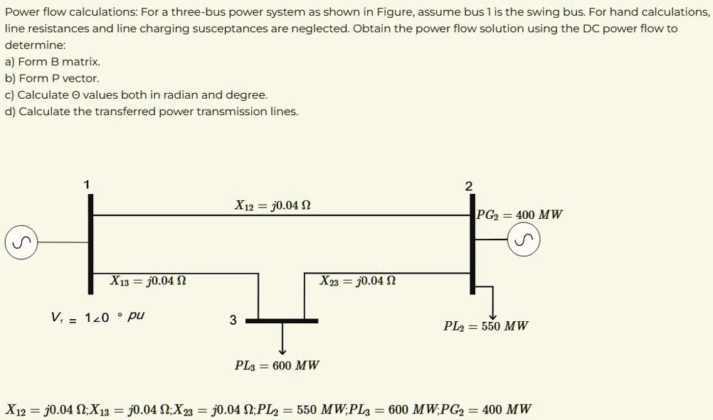
Solved Power Flow Calculations For A Three Bus Power System Chegg Understanding the flow of power between sending and receiving buses. how to derive formulas for complex power, real power (in watts), and reactive power (in vars). This version of the real valued power flow equations relates the voltages on the network in polar coordi nates to the power injections at each bus in rectangular coordinates:.

Solved Power Flow Calculations For A Three Bus Power System As Shown The reactive power flow equation is proportional to the circuit susceptance and the difference in voltage phasor magnitudes. the maximum difference in voltage phasor magnitudes will be on the order of 1.05 0.95=0.1. Calculate complex, real, and reactive power injected into each bus this can be done using 101 䠞 < and vectors and element by element multiplication (the .* operator. (part 1 of 5) power flow part 1: begin by learning to derive the formula for complex receiving power (sr) from the standard complex power formula and understanding key power. Since loads are more often expressed in terms of real (watts kw) and reactive (vars kvar) power, it is convenient to deal with transmission line equations in the form of sending and receiving end complex power and voltages.

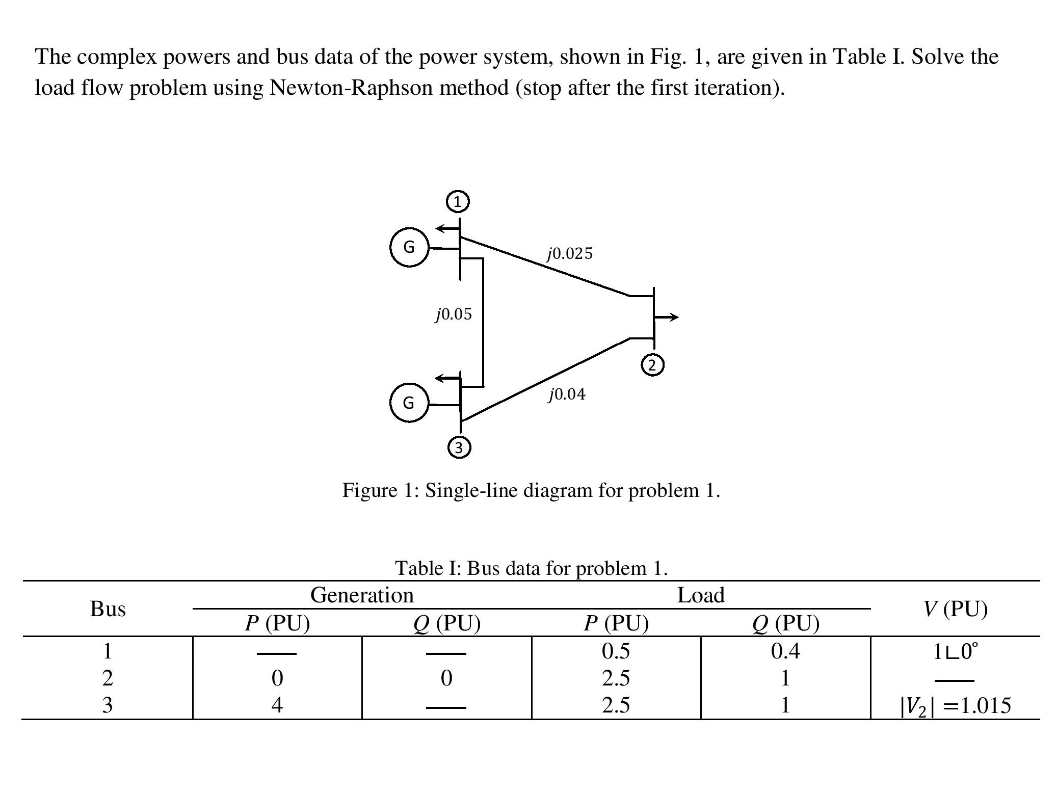
Solved The Complex Powers And Bus Data Of The Power System Chegg (part 1 of 5) power flow part 1: begin by learning to derive the formula for complex receiving power (sr) from the standard complex power formula and understanding key power. Since loads are more often expressed in terms of real (watts kw) and reactive (vars kvar) power, it is convenient to deal with transmission line equations in the form of sending and receiving end complex power and voltages. Predict power requirements in advance, using calendar and weather information in conjunction with prior experiences. make plans in advance to meet the predicted power needs while staying within the safe limits of the system and minimizing costs. In the simplest case of ac power transmission between two buses connected by a line (as shown in figure 1), the complex ac power flow at the receiving end bus can be calculated as follows:. Power flow is fundamental in electric power system analysis. given electric load and generation, we want to calculate the bus voltage and the power distribution [1]. in this example, we illustrate how to use solverz to symbolically model the power flow and then perform the power flow analysis. Power flow calculation is the most fundamental task in power system design and analysis. in this experiment, the power flow of a small industry system will be calculated using a computer program.

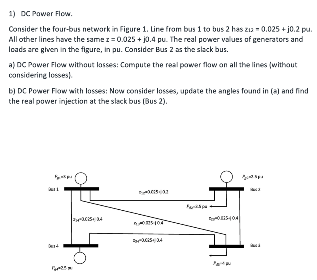
Solved 1 Dc Power Flow Consider The Four Bus Network In Chegg Predict power requirements in advance, using calendar and weather information in conjunction with prior experiences. make plans in advance to meet the predicted power needs while staying within the safe limits of the system and minimizing costs. In the simplest case of ac power transmission between two buses connected by a line (as shown in figure 1), the complex ac power flow at the receiving end bus can be calculated as follows:. Power flow is fundamental in electric power system analysis. given electric load and generation, we want to calculate the bus voltage and the power distribution [1]. in this example, we illustrate how to use solverz to symbolically model the power flow and then perform the power flow analysis. Power flow calculation is the most fundamental task in power system design and analysis. in this experiment, the power flow of a small industry system will be calculated using a computer program.
Comments are closed.