Half And Full Adder Logic Circuits

Combinational Logic Circuits Half Adder Full Circuit Diagram In this article we have gone through the half adder and full adder in brief with their logical expression and truth table, we have also seen difference between them in detail. In this article, the truth table and logic circuit of half and full adder, and how to design a full adder using half adder is explained.

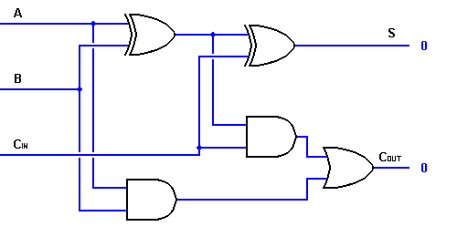
Half Adder And Full Adder Circuit Truth Table Full Adder Using Half Adder Half and full adder are used in combinational circuit design of microprocessor and we explained the truth table, circuit, and k map for both. Explore the differences between a half adder and a full adder, with comparison logic gates, inputs, outputs, and functionality in digital circuits. read more!. What is half adder and full adder circuit? the half adder circuit has two inputs: a and b, which add two input digits and generates a carry and a sum. the full adder circuit has three inputs: a and c, which add three input numbers and generates a carry and sum. Designing based on the equations, we get the following logic circuit for the half adder. how to design a full adder circuit? the only difference between a full adder and a half adder is that in a full adder, we also consider the carry input. so we have three inputs instead of two.

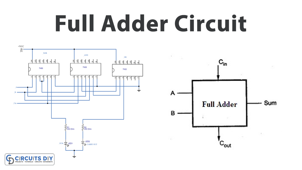
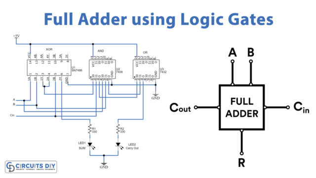
Half Full Adder Adder Logic Circuit Pptx What is half adder and full adder circuit? the half adder circuit has two inputs: a and b, which add two input digits and generates a carry and a sum. the full adder circuit has three inputs: a and c, which add three input numbers and generates a carry and sum. Designing based on the equations, we get the following logic circuit for the half adder. how to design a full adder circuit? the only difference between a full adder and a half adder is that in a full adder, we also consider the carry input. so we have three inputs instead of two. To illustrate how these circuits work, we can look at a half and full adder circuit diagram. a typical half adder circuit is represented by two logic gates connected in series. the inputs of the logic gates are labeled a and b, and the outputs (s and c) represent the sum and carry bits respectively. While full adder has a feature to carry current input to output from previous. here we will cover the differences between the half adder and full adder circuits and their truth table. Adders perform binary addition, a basic operation essential for all digital systems. they are integral components within cpus and alus, handling arithmetic and logic. enables complex data manipulation and processing in various digital applications. To overcome the above limitation faced with half adders, full adders are implemented. it is a arithmetic combinational logic circuit that performs addition of three single bits.

Design Logic Circuits Of Half Adder Full Adder Half Subtractor And To illustrate how these circuits work, we can look at a half and full adder circuit diagram. a typical half adder circuit is represented by two logic gates connected in series. the inputs of the logic gates are labeled a and b, and the outputs (s and c) represent the sum and carry bits respectively. While full adder has a feature to carry current input to output from previous. here we will cover the differences between the half adder and full adder circuits and their truth table. Adders perform binary addition, a basic operation essential for all digital systems. they are integral components within cpus and alus, handling arithmetic and logic. enables complex data manipulation and processing in various digital applications. To overcome the above limitation faced with half adders, full adders are implemented. it is a arithmetic combinational logic circuit that performs addition of three single bits.

Half Adder Circuit Using Logic Gates Adders perform binary addition, a basic operation essential for all digital systems. they are integral components within cpus and alus, handling arithmetic and logic. enables complex data manipulation and processing in various digital applications. To overcome the above limitation faced with half adders, full adders are implemented. it is a arithmetic combinational logic circuit that performs addition of three single bits.

Half Adder Circuit
Comments are closed.