Full Adder Using Two Half Circuit Diagram

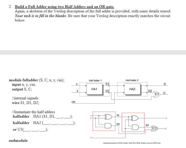
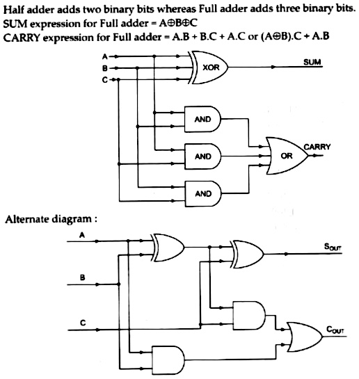
Full Adder Using Two Half Circuit Circuit Diagram Using two half adders to create a full adder can save time, space, and costs compared to creating a full adder from scratch. by combining the two halves, you can maximise the potential of the full adder and reduce the number of components needed to construct it. The block diagram of a full adder using two half adders is shown in figure 4. from the logic diagram of the full adder using half adders, it is clear that we require two xor gates, two and gates and one or gate for the implementation of a full adder circuit using half adders.

Full Adder Using Two Half Circuit Circuit Diagram Full adder is a combinational circuit that adds three inputs and produces two outputs. the first two inputs are a and b and the third input is an input carry as c in. Full adder is a combinational circuit which computer binary addition of three binary inputs. in this tutorial full adder using two half adder verilog code is explained. In this tutorial, we will learn about two important combinational logic circuits known as the half adder circuit and the full adder circuit. they are the basic building blocks of binary arithmetic circuits (the circuits which perform addition, subtraction, multiplication and division). Clear circuit diagrams and logical structure of half adder and full adder explained with truth tables, binary operations, and gate level design examples.

Full Adder Using Two Half Adders Circuit Diagram In this tutorial, we will learn about two important combinational logic circuits known as the half adder circuit and the full adder circuit. they are the basic building blocks of binary arithmetic circuits (the circuits which perform addition, subtraction, multiplication and division). Clear circuit diagrams and logical structure of half adder and full adder explained with truth tables, binary operations, and gate level design examples. A full adder is a digital circuit that performs the addition of three binary inputs. in this tutorial, you will learn how this circuit works, its truth table, and how to implement one using logic gates. Here's a step by step guide to drawing a full adder circuit diagram using two half adders. first, create a schematic diagram of your two half adders. these diagrams are simple representations of the individual circuits, showing their inputs and outputs. The expression for carry of two half adders is the same as that of a full adder. hence, when two half adders are connected, they behave as full adders and perform all the operations of a full adder. Design of full adder using half adder circuit is also shown. single bit full adder circuit and multi bit addition using full adder is also shown. before going into this subject, it is very important to know about boolean logic and logic gates. take a look : boolean logic. take a look : logic gates. take a look : flip flops. what is an adder?.

Full Adder Circuit Using Two Half Adders A full adder is a digital circuit that performs the addition of three binary inputs. in this tutorial, you will learn how this circuit works, its truth table, and how to implement one using logic gates. Here's a step by step guide to drawing a full adder circuit diagram using two half adders. first, create a schematic diagram of your two half adders. these diagrams are simple representations of the individual circuits, showing their inputs and outputs. The expression for carry of two half adders is the same as that of a full adder. hence, when two half adders are connected, they behave as full adders and perform all the operations of a full adder. Design of full adder using half adder circuit is also shown. single bit full adder circuit and multi bit addition using full adder is also shown. before going into this subject, it is very important to know about boolean logic and logic gates. take a look : boolean logic. take a look : logic gates. take a look : flip flops. what is an adder?.

Draw Full Adder Circuit Using Two Half Circuit Diagram The expression for carry of two half adders is the same as that of a full adder. hence, when two half adders are connected, they behave as full adders and perform all the operations of a full adder. Design of full adder using half adder circuit is also shown. single bit full adder circuit and multi bit addition using full adder is also shown. before going into this subject, it is very important to know about boolean logic and logic gates. take a look : boolean logic. take a look : logic gates. take a look : flip flops. what is an adder?.

Full Adder Using Half Circuit Circuit Diagram
Comments are closed.