Full Adder Explained Binary Addition Simplified In Under 5 Minutes Digital Electronics Ep 19

Digital Tutorial Lesson 5 Building A Reusable Digital Device Binary 🔢 full adder explained: binary addition simplified in under 5 minutes welcome back to our digital electronics series! 🚀 in this nineteenth episode, we dive into the. A full adder logic is designed in such a manner that can take eight inputs together to create a byte wide adder and cascade the carry bit from one adder to another.

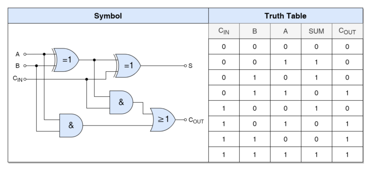
Binary Full Adder Diagram Quizlet In other words, a combinational circuit which is designed to add three binary digits and produces two outputs (sum and carry) is known as a full adder. thus, a full adder circuit adds three binary digits, where two are the inputs and one is the carry forwarded from the previous addition. In this article, we will explore the definition, importance, and implementation of full adder, as well as its applications in digital electronics. a full adder is a digital circuit that adds three one bit binary numbers, often used in the implementation of binary addition and subtraction circuits. Learn about full adder (combinational logic functions) in our free digital electronics textbook. The parallel adder is a type of combinational circuit used to perform the addition of the binary numbers. it is designed using the full adders connected in cascade form such that the output carry of each full adder is joined to the input carry of the subsequent full adder.

Binary Adder Electronics Lab Learn about full adder (combinational logic functions) in our free digital electronics textbook. The parallel adder is a type of combinational circuit used to perform the addition of the binary numbers. it is designed using the full adders connected in cascade form such that the output carry of each full adder is joined to the input carry of the subsequent full adder. In this tutorial, we are going to look at the binary adder and subtractor circuits. we will learn about the half adder, full adder, parallel adder (using multiple full adders), half subtractor, full subtractor and a parallel adder subtractor combination circuit. The document discusses adders in digital electronics, highlighting their role as fundamental components for binary addition in digital systems, particularly in processors and arithmetic logic units. Adders and subtractors are digital circuits used to perform arithmetic operations on binary numbers. an adder adds two binary values to produce a sum and often including a carry bit for values that exceed a single digit. ⚙️ full adder explained | complete binary addition using logic gates in this video, we dive into the full adder — an essential circuit in digital electronics that adds three.
Comments are closed.