Full Adder Circuit With The Logic Professor Computing Computerscience Electronics Logicgates

Full Adder Circuit Diagram With Logic Ic About press copyright contact us creators advertise developers terms privacy policy & safety how works test new features nfl sunday ticket © 2025 google llc. A full adder logic is designed in such a manner that can take eight inputs together to create a byte wide adder and cascade the carry bit from one adder to another.

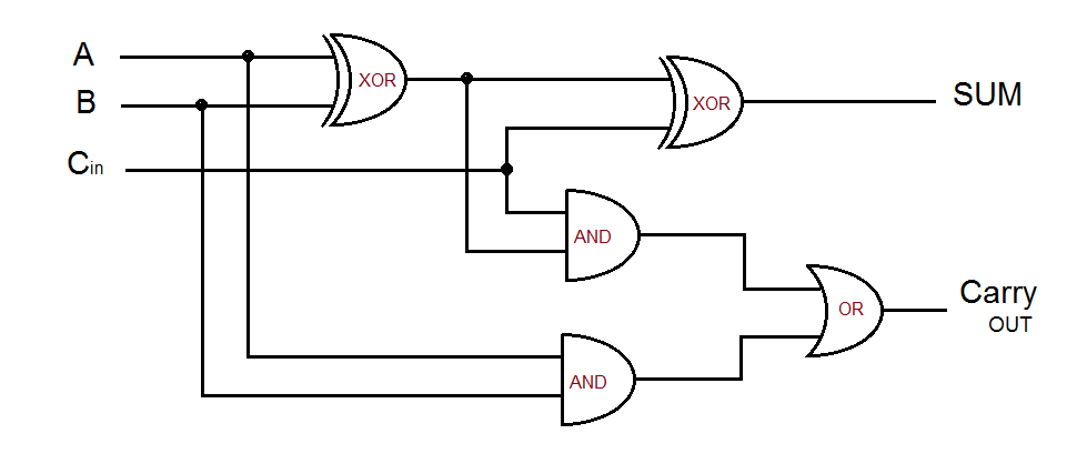
Module Ii Logic Gates And Adder Part 3 Pdf Logic Gate Electronic Here we will discuss a brief explanation of the working principle and the applications of a full adder circuit. it consists of two xor gates, two and gates, and an or gate, the logic gate circuit diagram is given below: full adder circuit diagram. To add larger numbers, we need a full adder a full adder is two half adders merged together with an or gate. the circuit takes three inputs two of the inputs are current values being added (a and b); the third input indicates whether or not there is a carry coming in from the previous column. A full adder is a digital circuit that performs the addition of three binary inputs. in this tutorial, you will learn how this circuit works, its truth table, and how to implement one using logic gates. Designing a full adder circuit using logic gates isn't difficult but it does require some knowledge and understanding of the capabilities of logic gates. a full adder is one of the most basic and widely used digital circuits, and is primarily used to add two binary numbers together.

2019 Adder Pdf Logic Gate Cmos A full adder is a digital circuit that performs the addition of three binary inputs. in this tutorial, you will learn how this circuit works, its truth table, and how to implement one using logic gates. Designing a full adder circuit using logic gates isn't difficult but it does require some knowledge and understanding of the capabilities of logic gates. a full adder is one of the most basic and widely used digital circuits, and is primarily used to add two binary numbers together. The 8 bit adder is a digital circuit designed to perform the addition of two 8 bit binary numbers. built using basic logic gates such as and, or, and xor gates, this circuit is a fundamental component in computer arithmetic and is often used in processors, calculators, and other digital systems. Explore the design and implementation of full adder circuits, fundamental components in digital arithmetic. this guide explains the functionality of full adders, their boolean algebra representation, simplification using karnaugh maps (k maps), and their construction using logic gates. To build a full adder, add twice: (a b) carryin (this is why we call the simpler piece a half adder.) we have a carry if there was a carry in the two add operations!. When we draw a lot of logic gates the circuit starts to get confusing, so we simplify it by using blocks to represent groups of logic gates that are repeated. here we represent the bunch of logic gates for full adders and a half adder using a square but don't actually draw the gates.
Comments are closed.