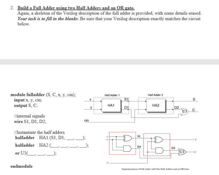
Full Adder Circuit Using 2 Half Adders Circuit Diagram

Full Adder Circuit Using 2 Half Adders Circuit Diagram A full adder circuit is a complex but vital component of digital design that adds two binary numbers together and produces an output of "0" or "1" in response. it is commonly used in calculators, computers, and other electronic gadgets. Aoa everyone in this post i have made a 2 bit full adder using 2 half adders. this project has been made by saad ahmad malik and muhammad adil. what supplies do i need? and how can i make this circuit? all your questions will be answered down below.

Full Adder Circuit Using 2 Half Adders Circuit Diagram In this tutorial, we will learn about two important combinational logic circuits known as the half adder circuit and the full adder circuit. they are the basic building blocks of binary arithmetic circuits (the circuits which perform addition, subtraction, multiplication and division). Full adder using half adders with this logic circuit, two bits can be added together, taking a carry from the next lower order of magnitude, and sending a carry to the next higher order of magnitude. Thus, we can implement a full adder circuit with the help of two half adder circuits. the first will half adder will be used to add a and b to produce a partial sum. Half and full adder are used in combinational circuit design of microprocessor and we explained the truth table, circuit, and k map for both.

Full Adder Circuit Using Two Half Adders Thus, we can implement a full adder circuit with the help of two half adder circuits. the first will half adder will be used to add a and b to produce a partial sum. Half and full adder are used in combinational circuit design of microprocessor and we explained the truth table, circuit, and k map for both. Detailed explanation of half adder and full adder circuit diagrams, showing their components, operation principles, and differences in binary addition. Uses two half adders to make a full adder. a cpu contains several single memory locations called registers. addition involves adding 2 registers, 1 bit at a time, to produce an answer in a 3rd register. this is a 3 bit ripple adder with a full adder at each bit position. Half adders have the following truth table and logic circuit. what are the input ports. what are the output ports. implement the sum and carry equations using verilog bit operators. the verilog code can be written in structural modelling for the above circuit. declare the full adder verilog module. what are the input ports. Here's a step by step guide to drawing a full adder circuit diagram using two half adders. first, create a schematic diagram of your two half adders. these diagrams are simple representations of the individual circuits, showing their inputs and outputs.

Full Adder Using Two Half Adders Circuit Diagram Detailed explanation of half adder and full adder circuit diagrams, showing their components, operation principles, and differences in binary addition. Uses two half adders to make a full adder. a cpu contains several single memory locations called registers. addition involves adding 2 registers, 1 bit at a time, to produce an answer in a 3rd register. this is a 3 bit ripple adder with a full adder at each bit position. Half adders have the following truth table and logic circuit. what are the input ports. what are the output ports. implement the sum and carry equations using verilog bit operators. the verilog code can be written in structural modelling for the above circuit. declare the full adder verilog module. what are the input ports. Here's a step by step guide to drawing a full adder circuit diagram using two half adders. first, create a schematic diagram of your two half adders. these diagrams are simple representations of the individual circuits, showing their inputs and outputs.

Full Adder Using Two Half Circuit Circuit Diagram Half adders have the following truth table and logic circuit. what are the input ports. what are the output ports. implement the sum and carry equations using verilog bit operators. the verilog code can be written in structural modelling for the above circuit. declare the full adder verilog module. what are the input ports. Here's a step by step guide to drawing a full adder circuit diagram using two half adders. first, create a schematic diagram of your two half adders. these diagrams are simple representations of the individual circuits, showing their inputs and outputs.

Full Adder Circuit Using Two Half
Comments are closed.