Full Adder Circuit Logicly Circuit Diagram

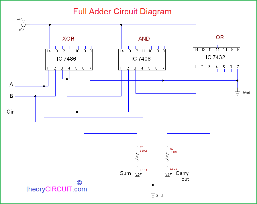
Full Adder Circuit Diagram Circuit Theory Electronics Circuit Tutorial Instead of needing to build a complex system of gates and logic circuits, you can achieve the same effect with a single full adder circuit. this reduces cost and increases reliability, since there are fewer components that can fail. Here three input and two output full adder circuit diagram explained with logic gates circuit and also logic ic circuits.

Full Adder Circuit Diagram Theorycircuit Do It Yourself Electronics A full adder is a digital circuit that performs the addition of three binary inputs. in this tutorial, you will learn how this circuit works, its truth table, and how to implement one using logic gates. Full adder is a combinational circuit that adds three inputs and produces two outputs. the first two inputs are a and b and the third input is an input carry as c in. the output carry is designated as c out and the normal output is designated as s which is sum. Most digital circuits that perform addition or subtraction use a full adder circuit. it gets its name from the fact that it adds two binary digits plus a carry in digit to generate a total and carry out digit. The circuit diagram shows all the connections needed to make a full adder out of 9 nand gates. this shows all the connections need to make the circuit including the ground connections.
Full Adder Circuit Diagram Using Basic Gates Most digital circuits that perform addition or subtraction use a full adder circuit. it gets its name from the fact that it adds two binary digits plus a carry in digit to generate a total and carry out digit. The circuit diagram shows all the connections needed to make a full adder out of 9 nand gates. this shows all the connections need to make the circuit including the ground connections. Circuit diagram of a full adder with clear explanation of logic gates, binary addition, and truth table. useful for electronics and digital logic study or reference. Thus, a full adder circuit adds three binary digits, where two are the inputs and one is the carry forwarded from the previous addition. the block diagram and circuit diagram of the full adder are shown in figure 1. Logisim is a free and open source software for creating and simulating digital logic circuits. this software contains a pre built full adder circuit logisim component which makes using it easy and efficient. the circuit is designed so users can easily construct and simulate logic circuits. Explore the full adder truth table and detailed circuit diagram, explaining how inputs combine to produce sum and carry outputs in binary addition.

Logic Circuit Diagram For Full Adder Circuit Diagram Circuit diagram of a full adder with clear explanation of logic gates, binary addition, and truth table. useful for electronics and digital logic study or reference. Thus, a full adder circuit adds three binary digits, where two are the inputs and one is the carry forwarded from the previous addition. the block diagram and circuit diagram of the full adder are shown in figure 1. Logisim is a free and open source software for creating and simulating digital logic circuits. this software contains a pre built full adder circuit logisim component which makes using it easy and efficient. the circuit is designed so users can easily construct and simulate logic circuits. Explore the full adder truth table and detailed circuit diagram, explaining how inputs combine to produce sum and carry outputs in binary addition.
Comments are closed.