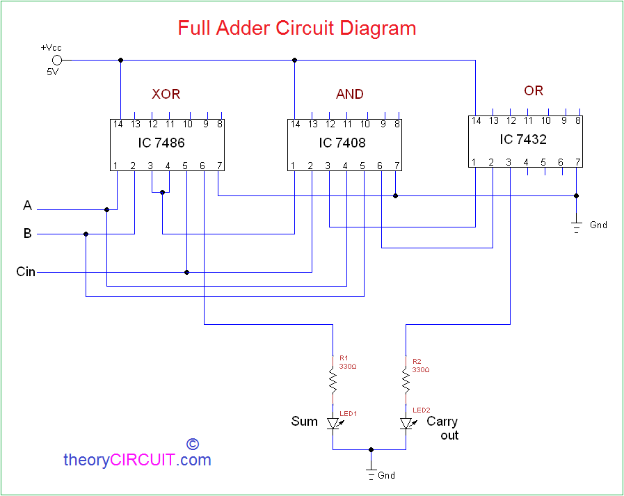
Full Adder Circuit Diagram A Complete Tutorial Edrawmax

Full Adder Circuit Diagram A Complete Tutorial Edrawmax 2022 This section will practically implement the full adder circuit diagram, truth table, and equation. and will know the process of making a full adder in three ways. In this tutorial, we discussed all the key concepts related to full adders in digital electronics.
Circuit Diagram Of Full Adder Circuit Diagram It provides a workspace for creating over 280 types of diagrams, including flowcharts, fishbone diagrams, uml diagrams, floor plans, and more. A full adder circuit allows for the sum of two input numbers to be calculated and outputted in a single operation. the most popular full adder circuit diagram comprises three inputs including two summer inputs and a carry input. A full adder is a digital circuit that performs the addition of three binary inputs. in this tutorial, you will learn how this circuit works, its truth table, and how to implement one using logic gates. Full adder is a combinational circuit that adds three inputs and produces two outputs. the first two inputs are a and b and the third input is an input carry as c in. the output carry is designated as c out and the normal output is designated as s which is sum.

Circuit Diagram For Full Adder Circuit Diagram A full adder is a digital circuit that performs the addition of three binary inputs. in this tutorial, you will learn how this circuit works, its truth table, and how to implement one using logic gates. Full adder is a combinational circuit that adds three inputs and produces two outputs. the first two inputs are a and b and the third input is an input carry as c in. the output carry is designated as c out and the normal output is designated as s which is sum. Circuit diagram of a full adder with clear explanation of logic gates, binary addition, and truth table. useful for electronics and digital logic study or reference. The full adder takes two inputs along with an input carry and generates a sum bit and a carry bit as output. the difference between the full adder and a half adder is that the full adder accepts a carry bit as an input. The article deals about the full adder circuit with the basic gates, truth table, equations and the verilog code. the applications are also discussed. The ‘combinational circuit’ which is capable of performing addition on three input bits that is two inputs and the carry in from the previous operation is known as full adder.

Full Adder Circuit Diagram Theorycircuit Do It Yourself Electronics Circuit diagram of a full adder with clear explanation of logic gates, binary addition, and truth table. useful for electronics and digital logic study or reference. The full adder takes two inputs along with an input carry and generates a sum bit and a carry bit as output. the difference between the full adder and a half adder is that the full adder accepts a carry bit as an input. The article deals about the full adder circuit with the basic gates, truth table, equations and the verilog code. the applications are also discussed. The ‘combinational circuit’ which is capable of performing addition on three input bits that is two inputs and the carry in from the previous operation is known as full adder.

Full Adder Circuit Diagram Basic Circuit Circuit Diagram Seekic The article deals about the full adder circuit with the basic gates, truth table, equations and the verilog code. the applications are also discussed. The ‘combinational circuit’ which is capable of performing addition on three input bits that is two inputs and the carry in from the previous operation is known as full adder.
Comments are closed.