Differentiate Between Half Adder And Full Adder Draw The Logic Ci
Differentiate Between Half Adder And Full Adder Draw The Logic Circuit In this article we have gone through the half adder and full adder in brief with their logical expression and truth table, we have also seen difference between them in detail. One of the main advantage of using half adders and full adders in the digital circuits is that they are designed by using logic gates that process the input data very fast.
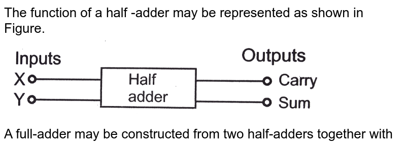
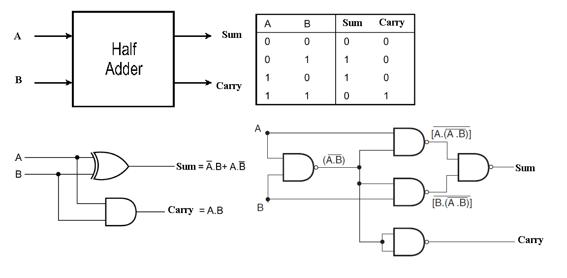
Differentiate Between Half Adder And Full Adder Draw The Logic Circuit There is a primary difference between half adder and full adder. half adder only adds the current inputs as 1 bit numbers and does not focus on the previous inputs. on the other hand, full adder can easily carry the current inputs as well as the output from the previous additions. The half adder circuit operation needs two binary inputs : augend and addend bits; and two binary outputs : sum and carry. the half adder truth table shown in 3.6 gives the relation between input and output variables for half adder circuit operation. Both the half adder and full adder are combinational logic circuits that perform addition on two binary bits. however, they differ in their ability to handle carry operations and the number of bits they can add. Explore the differences between a half adder and a full adder, with comparison logic gates, inputs, outputs, and functionality in digital circuits. read more!.

Differentiate Between Half Adder And Full Adder Draw The Logic Ci Both the half adder and full adder are combinational logic circuits that perform addition on two binary bits. however, they differ in their ability to handle carry operations and the number of bits they can add. Explore the differences between a half adder and a full adder, with comparison logic gates, inputs, outputs, and functionality in digital circuits. read more!. Discover the differences between half adder vs full adder. learn their roles in digital circuits and how they perform binary addition. What is a full adder? a full adder is an advanced combinational circuit in digital electronics that enhances the functionality of a half adder by permitting the addition of three input variables: two significant bits and one carry input. To illustrate how these circuits work, we can look at a half and full adder circuit diagram. a typical half adder circuit is represented by two logic gates connected in series. the inputs of the logic gates are labeled a and b, and the outputs (s and c) represent the sum and carry bits respectively. Detailed explanation of half adder and full adder circuit diagrams, showing their components, operation principles, and differences in binary addition.

Differentiate Between Half Adder And Full Adder Draw The Logic Circuit Discover the differences between half adder vs full adder. learn their roles in digital circuits and how they perform binary addition. What is a full adder? a full adder is an advanced combinational circuit in digital electronics that enhances the functionality of a half adder by permitting the addition of three input variables: two significant bits and one carry input. To illustrate how these circuits work, we can look at a half and full adder circuit diagram. a typical half adder circuit is represented by two logic gates connected in series. the inputs of the logic gates are labeled a and b, and the outputs (s and c) represent the sum and carry bits respectively. Detailed explanation of half adder and full adder circuit diagrams, showing their components, operation principles, and differences in binary addition.

Differentiate Between Half Adder And Full Adder Draw The Logic Circuit To illustrate how these circuits work, we can look at a half and full adder circuit diagram. a typical half adder circuit is represented by two logic gates connected in series. the inputs of the logic gates are labeled a and b, and the outputs (s and c) represent the sum and carry bits respectively. Detailed explanation of half adder and full adder circuit diagrams, showing their components, operation principles, and differences in binary addition.

Differentiate Between Half Adder And Full Adder Draw The Logic Circuit
Comments are closed.