Designing Full Subtractor Using Nor Gate Digital Circuits And Logic Design

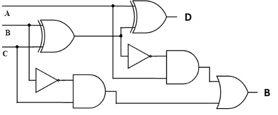
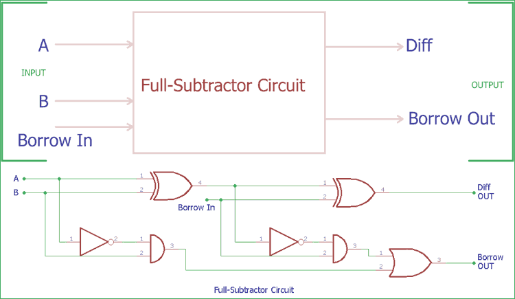
Full Subtractor Using Nor Gate Circuit Diagram Wiring Digital And Designing full subtractor using nor gate digital circuits and logic design jeevan safal 6.88k subscribers subscribed. In this article, we’ll look at how the full subtractor works by analyzing the circuit diagram of a full subtractor using nor gate. the circuit diagram of a full subtractor using nor gate consists of three inputs (a, b, and c), and two outputs (d and b).

Full Subtractor Using Nor Gate Circuit Diagram Wiring Digital And Overall, the circuit diagram of a full subtractor using nor gates is an essential piece of knowledge for any electrical engineer or computer scientist. with its simple design and efficient performance, it is no wonder why this circuit is so popular. This is because real time scenarios involve subtracting the multiple number of bits which can not be accomplished using half subtractors. to overcome this drawback, full subtractor comes into play. Explore digital circuits online with circuitverse. with our easy to use simulator interface, you will be building circuits in no time. Adders and subtractors are digital circuits used to perform arithmetic operations on binary numbers. an adder adds two binary values to produce a sum and often including a carry bit for values that exceed a single digit.

Full Subtractor Using Nor Gate Circuit Diagram Wiring Digital And Explore digital circuits online with circuitverse. with our easy to use simulator interface, you will be building circuits in no time. Adders and subtractors are digital circuits used to perform arithmetic operations on binary numbers. an adder adds two binary values to produce a sum and often including a carry bit for values that exceed a single digit. In this paper, reversible 8 bit parallel binary adder subtractor with design i, design ii and design iii are proposed. in all the three design approaches, the full adder and subtractors are realized in a single unit as compared to only full subtractor in the existing design. This article gives a full subtractor theory idea which comprises the premises like what is a subtractor, design with logic gates, truth table, etc. this article is useful for engineering students who can go through these topics in the hdl practical lab. The article describes the circuit connections based on the logic gates and the boolean expression,truth table and k map analysis for the full subtractor. A subtractor is an electronic logic circuit used for calculating the difference between two binary numbers. a full subtractor displays this calculation with three inputs and generated output; difference and borrow.
Full Subtractor Using Nor Gate Circuit Diagram Wiring Digital And In this paper, reversible 8 bit parallel binary adder subtractor with design i, design ii and design iii are proposed. in all the three design approaches, the full adder and subtractors are realized in a single unit as compared to only full subtractor in the existing design. This article gives a full subtractor theory idea which comprises the premises like what is a subtractor, design with logic gates, truth table, etc. this article is useful for engineering students who can go through these topics in the hdl practical lab. The article describes the circuit connections based on the logic gates and the boolean expression,truth table and k map analysis for the full subtractor. A subtractor is an electronic logic circuit used for calculating the difference between two binary numbers. a full subtractor displays this calculation with three inputs and generated output; difference and borrow.
Comments are closed.