Design Mod 10 Synchronous Counter Using Jkff Sequential Logic Circuit Digital Circuit Design

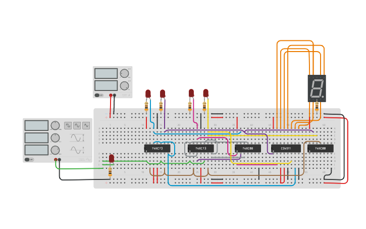
Circuit Design Synchronous Bcd Counter Using Jkff Tinkercad Learn the intricate process of creating a design mod 10 synchronous counter using jk flip flops in this comprehensive guide to sequential logic circuits and digital circuit. To avoid lock out and make sure that at the starting point the counter is in its initial state or it comes to its initial state within few clock cycles, external logic circuitry is to be provided and so we design the counter assuming the next state to be the initial state, from each unused states.

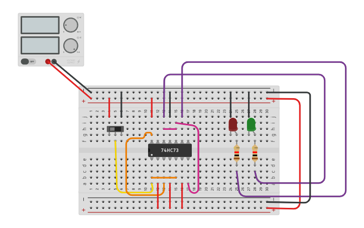
Circuit Design 2 Bit Synchronous Using Jkff Tinkercad This 4 bit digital counter is a sequential circuit that uses jk flipflops, and gates, and a digital clock. for each clock tick, the 4 bit output increments by one. Mod 10 counters are also referred to as decade counters or bcd counters. in this project, i used a jk flipflop as a counter and an astable multivibrator to generate the clock signal. Let’s not have an input to trigger each count, but instead let’s act as the clock by substituting a push button switch tied to the positive terminal of our power supply (which is equivalent to a logic 1). A synchronous mod 10 (decimal) counter can be built from binary counters by adding logic to reset the count to 0 after reaching 10. this is achieved by detecting the 1001 state and toggling an additional flip flop on the next clock pulse.

Design A Synchronous Sequential Circuit Using Jk Flip Flop Let’s not have an input to trigger each count, but instead let’s act as the clock by substituting a push button switch tied to the positive terminal of our power supply (which is equivalent to a logic 1). A synchronous mod 10 (decimal) counter can be built from binary counters by adding logic to reset the count to 0 after reaching 10. this is achieved by detecting the 1001 state and toggling an additional flip flop on the next clock pulse. The design steps are somewhat similar for both synchronous counter and asynchronous counter but differ slightly. follow the below given steps to design the synchronous counter. A synchronous finite state machine changes state only when the appropriate clock edge occurs. the following diagram shows a sequential circuit that consists of a combinational logic block and a memory block. for simplicity, we limit the design to one input and 2 jk flip flops. This video provides you with a detailed understanding of design mod 10 synchronous counter using jkff. Design a mod 10 synchronous counter using jk flip flops. a. draw the logic circuit b. draw the waveform timing diagram and obtain the sequence of the numbers. in the timing diagram, indicate the time instance when the counter is reset to achieve mod 10. your solution’s ready to go!.

Solved You Want To Design A Synchronous Counter Sequential Chegg The design steps are somewhat similar for both synchronous counter and asynchronous counter but differ slightly. follow the below given steps to design the synchronous counter. A synchronous finite state machine changes state only when the appropriate clock edge occurs. the following diagram shows a sequential circuit that consists of a combinational logic block and a memory block. for simplicity, we limit the design to one input and 2 jk flip flops. This video provides you with a detailed understanding of design mod 10 synchronous counter using jkff. Design a mod 10 synchronous counter using jk flip flops. a. draw the logic circuit b. draw the waveform timing diagram and obtain the sequence of the numbers. in the timing diagram, indicate the time instance when the counter is reset to achieve mod 10. your solution’s ready to go!.

Solved B Design A Mod 10 Synchronous Counter Using Jk Flip Chegg This video provides you with a detailed understanding of design mod 10 synchronous counter using jkff. Design a mod 10 synchronous counter using jk flip flops. a. draw the logic circuit b. draw the waveform timing diagram and obtain the sequence of the numbers. in the timing diagram, indicate the time instance when the counter is reset to achieve mod 10. your solution’s ready to go!.
Comments are closed.