Default Digital Analog Pin State Input Or Output Do Unused Pins

Default Digital Analog Pin State Input Or Output Do Unused Pins So it sounds like the best solution is either manually define all unused pins as inputs and connect them to 5v or ground via resistor, or set as output and leave unconnected. The official nxp recommendation for unused kinetis gpio pins is to leave them disconnected from the board (no bias) and in their default state. this means that the digital gpio pin is in its disabled state (input and output buffers disabled) or configured as an analog channel.

Using Arduino Analog Pins As Digital Output Input Pins To minimize power consumption, enable pull up or down on all unused pins, and disable the digital input buffer on pins that are connected to analog sources. if you search the interwebs on this topic, you'll find a lot of different opinions. If i have a fpga chip which has 500 gpio pins, i use 100 pins of them. the left 400 gpio pins are not in my design so i don't do any configuration for them (no any constrain in constrain files). When unused digital inputs are left unconnected they will float, which can cause both unexpected logic behavior and excessive current draw. essentially, a cmos digital input circuit uses mosfet transistors in pairs (see below figure). High impedance analog mode is the default reset state; both output driver and digital input buffer are turned off. this state prevents an external voltage from causing a current to flow into the digital input buffer.

Using Arduino Analog Pins As Digital Output Input Pins When unused digital inputs are left unconnected they will float, which can cause both unexpected logic behavior and excessive current draw. essentially, a cmos digital input circuit uses mosfet transistors in pairs (see below figure). High impedance analog mode is the default reset state; both output driver and digital input buffer are turned off. this state prevents an external voltage from causing a current to flow into the digital input buffer. The default as input (or analog input as applicable) to prevent the io contentions that would happen if they were outputs at power up. if you have a dedicated input and no space for pullups you can tie it to an output. Connecting unused pins directly to vcc or gnd is not recommended, since this may cause excessive currents if the pin is accidentally configured as an output. in other words setting unused pins as input pullup is the best practice as op says. Digital circuitry often has inputs that are used to configure its operation and are permanently connected to logic 0 or logic 1. although such inputs never change their logical state, they are not unused and must be connected as the device operation requires. In the reset state (i.e. default, left unconfigured), the pins are on this mcu configured as digital io pins. you need to define them as analog mode, digital inputs with pull resistor, or define them as outputs.

Arduino Use Analog Pins As Digital Pin 43 Off The default as input (or analog input as applicable) to prevent the io contentions that would happen if they were outputs at power up. if you have a dedicated input and no space for pullups you can tie it to an output. Connecting unused pins directly to vcc or gnd is not recommended, since this may cause excessive currents if the pin is accidentally configured as an output. in other words setting unused pins as input pullup is the best practice as op says. Digital circuitry often has inputs that are used to configure its operation and are permanently connected to logic 0 or logic 1. although such inputs never change their logical state, they are not unused and must be connected as the device operation requires. In the reset state (i.e. default, left unconfigured), the pins are on this mcu configured as digital io pins. you need to define them as analog mode, digital inputs with pull resistor, or define them as outputs.

Could Digital Pin 6 Output Interfere With Analog Pin 6 Input Classic Digital circuitry often has inputs that are used to configure its operation and are permanently connected to logic 0 or logic 1. although such inputs never change their logical state, they are not unused and must be connected as the device operation requires. In the reset state (i.e. default, left unconfigured), the pins are on this mcu configured as digital io pins. you need to define them as analog mode, digital inputs with pull resistor, or define them as outputs.

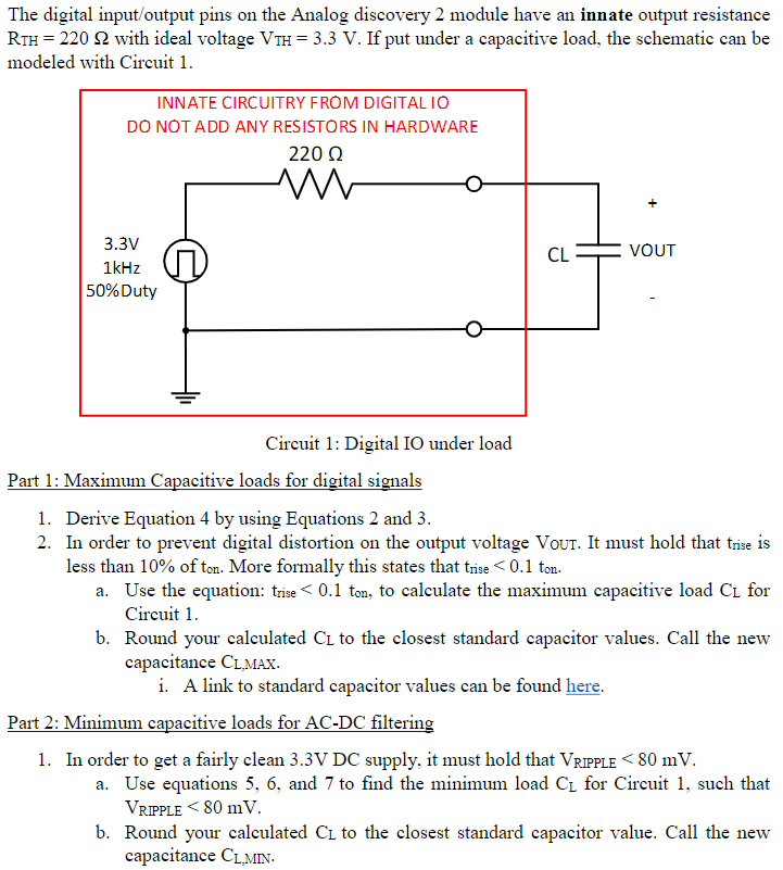
Solved The Digital Input Output Pins On The Analog Discovery Chegg
Comments are closed.