De Embedding Measured Load Pull Data Using Em Analysis Of A Fixture

Measured And De Embedded Data Compared With Simulation Results Using In this is a video clip, matt ozalas describes how to enhance analysis of measured data using simulation data. The de embedding process will then be detailed for removing the effects of a test fixture placed between the measurement and device planes. also included will be a description of how the same process can be used to embed a hypothetical or “virtual” network into the measurement of the dut.

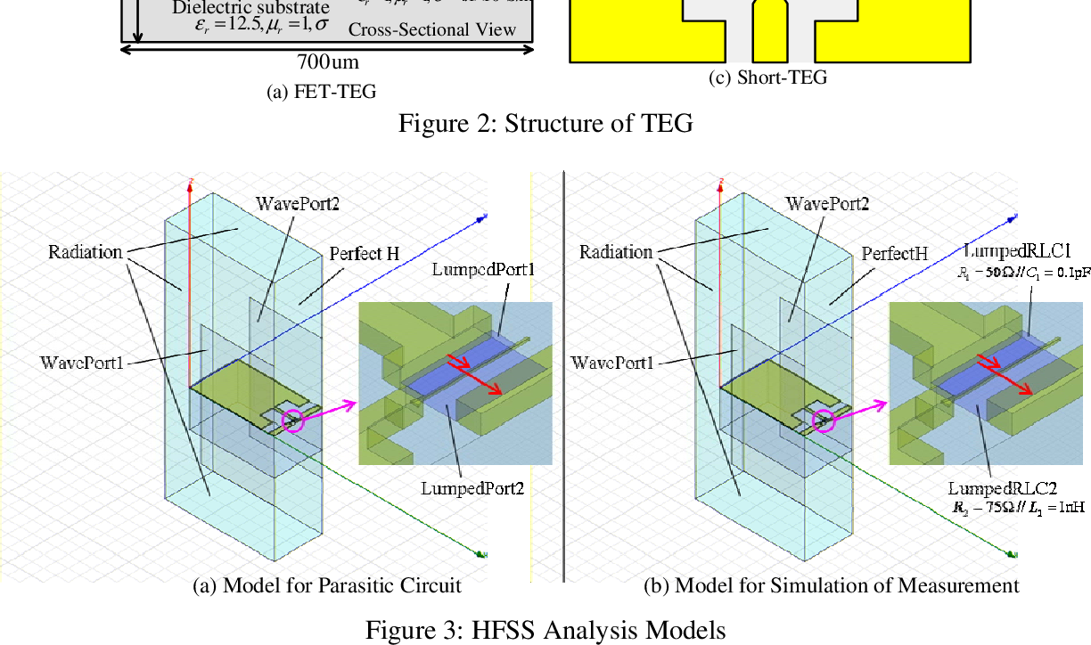
Figure 3 From De Embedding Method Using Em Simulator For Device De embedding makes the murky waters between the si engineer and the dut clear by removing the fixture from the measurement. de embedding isolates the dut using an algorithm that mathematically removes the test fixture from the measurement. This application note provides practical hints to accurately characterize and de embed these lead in and lead out structures with r&s vector network analyzers zna, znb, znbt and znd. We describe a hybrid de embedding method that can achieve a good balance between accuracy and the number of standards required. in this new approach, the characterization of a fixture is based on a combination of electromagnetic (em) simulation and measurement. Figure 5 port extension settings with loss figure 6 port extension with loss compensation while port extension corrects the delay and phase to the dut and may also correct for a certain amount of loss, de embedding provides a full correction, point by point over the entire frequency range.

De Embedding Technique Using Automatic Fixture Removal Afr Case Study We describe a hybrid de embedding method that can achieve a good balance between accuracy and the number of standards required. in this new approach, the characterization of a fixture is based on a combination of electromagnetic (em) simulation and measurement. Figure 5 port extension settings with loss figure 6 port extension with loss compensation while port extension corrects the delay and phase to the dut and may also correct for a certain amount of loss, de embedding provides a full correction, point by point over the entire frequency range. Whether a simplified model, such as a length of ideal transmission line, or a complex model, created using an em simulator, is used for the test fixture, it is now necessary to perform the de embedding process using this s parameter model. Understanding, implementing, and utilizing this de embedding method has the potential to reduce test fixture cost, reduce likelihood of measurement error, and increase the accuracy of dut characterization. Accurate vector network analyzer (vna) measurement of a device under test (dut) mounted on a printed circuit board fixture requires some form of de embedding to eliminate the effects of the fixturing. Obtaining accurate impedance measurements is dependent on proper calibration, embedding, and de embedding of the instrument, cables and fixtures. in this session we will show:.

Test Fixture De Embedding 101 2017 06 16 Signal Integrity Journal Whether a simplified model, such as a length of ideal transmission line, or a complex model, created using an em simulator, is used for the test fixture, it is now necessary to perform the de embedding process using this s parameter model. Understanding, implementing, and utilizing this de embedding method has the potential to reduce test fixture cost, reduce likelihood of measurement error, and increase the accuracy of dut characterization. Accurate vector network analyzer (vna) measurement of a device under test (dut) mounted on a printed circuit board fixture requires some form of de embedding to eliminate the effects of the fixturing. Obtaining accurate impedance measurements is dependent on proper calibration, embedding, and de embedding of the instrument, cables and fixtures. in this session we will show:.
Comments are closed.