4 Bit Down Binary Counter Using Proteus Design An Chegg

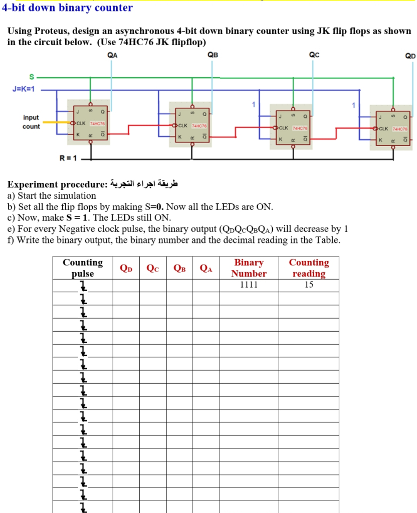
Design 4 Bit Binary Counter With Parallel Load Using Nanometric Question: 4 bit down binary counter using proteus, design an asynchronous 4 bit down binary counter using jk flip flops as shown in the circuit below. 4 bit binary counter using d flip flops circuit, simulation, and pcb layout design using proteus ide. more.

Solved 4 Bit Down Binary Counter Using Proteus Design A This repository contains a complete proteus simulation project for a 4 bit synchronous counter rahimatariq7 counter. Therefore, this type of counter is also known as a 4 bit synchronous up counter. however, we can easily construct a 4 bit synchronous down counter by connecting the and gates to the q output of the flip flops as shown to produce a waveform timing diagram the reverse of the above. Here we are going to use t flip flops, which are built using d flip flops. the t flip flops act as a toggle switch. when the input is 0, there is no change in the. output of the t flip flops. it retains the previous value. but when the input is 1, the output is. complemented. The document describes two experiments on counting circuits using jk flip flops in proteus: 1) a 4 bit down asynchronous counter that counts from 15 to 0 on negative clock pulses is designed. the output states are recorded in a table.

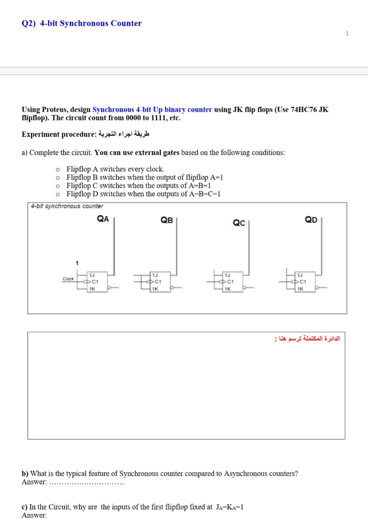
Solved Q2 4 Bit Synchronous Counter Using Proteus Design Chegg Here we are going to use t flip flops, which are built using d flip flops. the t flip flops act as a toggle switch. when the input is 0, there is no change in the. output of the t flip flops. it retains the previous value. but when the input is 1, the output is. complemented. The document describes two experiments on counting circuits using jk flip flops in proteus: 1) a 4 bit down asynchronous counter that counts from 15 to 0 on negative clock pulses is designed. the output states are recorded in a table. In this video i explain how to simulation 4 bit synchronous down counter by using j k flip flop. Record the binary output and the corresponding decimal reading in a table for each count as you observe the leds. your table should start with the initial state 1111 (decimal 15) and decrement by 1 with each clock pulse. 4 bit synchronous up down counter (74192) implements a 4 bit up down binary counter using the 74192 ic. up and down controls for increment decrement. leds represent binary output (00 to 99). synchronous operation ensures accurate toggling. To start constructing the 4 bit synchronous binary down counter in proteus, place four jk flip flops (jkff) on your schematic and label them u1, u2, u3, and u4.

Solved Construct The 4 Bit Synchronous Binary Down Counter Chegg In this video i explain how to simulation 4 bit synchronous down counter by using j k flip flop. Record the binary output and the corresponding decimal reading in a table for each count as you observe the leds. your table should start with the initial state 1111 (decimal 15) and decrement by 1 with each clock pulse. 4 bit synchronous up down counter (74192) implements a 4 bit up down binary counter using the 74192 ic. up and down controls for increment decrement. leds represent binary output (00 to 99). synchronous operation ensures accurate toggling. To start constructing the 4 bit synchronous binary down counter in proteus, place four jk flip flops (jkff) on your schematic and label them u1, u2, u3, and u4.
Comments are closed.